Week 9 - Parametric study on Gate valve.
AIM: To perform the parametric study on the gate valve simulation by setting the opening from 10% to 80%.
THEORY:
- What is a gate valve?
A gate valve is a valve that opens by lifting a barrier out of the path of the fluid. By lifting, the gate disc user is able to increase the mass flow rate of the fluid in flow. Thus, a gate valve helps regulating mass flow rate within a pipe.
PRE-PROCESSING:
- We will first upload the geometry given to us into spaceclaim.
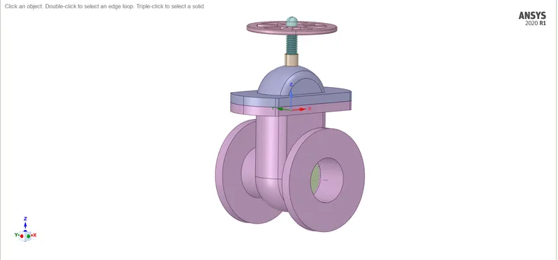
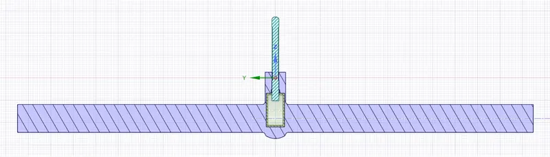
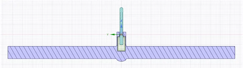
- As per the question, we need to study the flow with varying the gate opening from 10% to 80%. In order to do that, we will parameterize the gate disc.
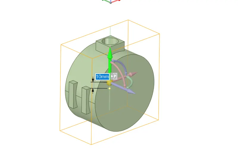
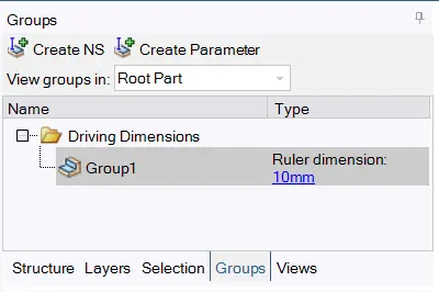
- The "P" icon shown next to the distance is used to parameterise the component. We have now parameterized the gate disc thus a seperate group will be created in the "Groups" window.
- After we have set our parameterised condition, lets move ahead and extract the fluid volume.
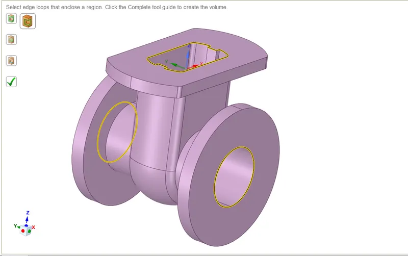
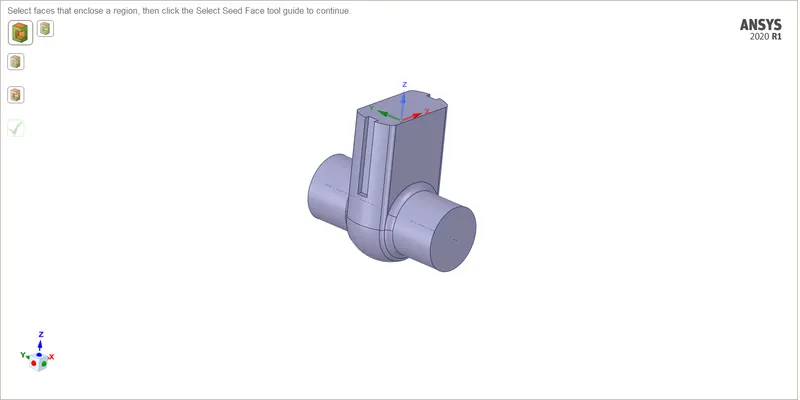
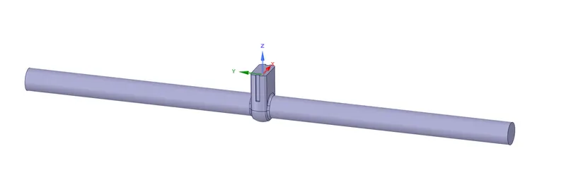
- The image shown above shows the extracted fluid volume. We will extend the inlet and outlet pipes in order to observe flow better.
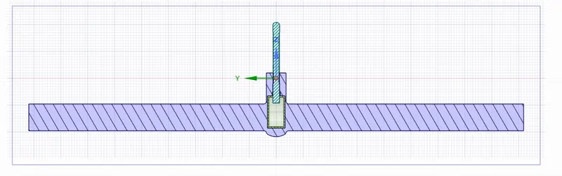
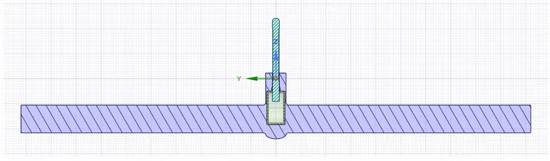
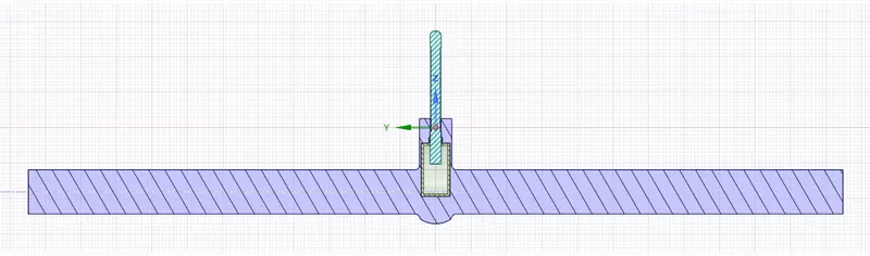
- The image given below shows the sectional view to understand the opening of gate disc.
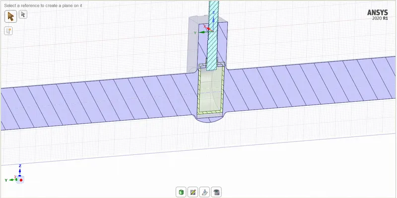
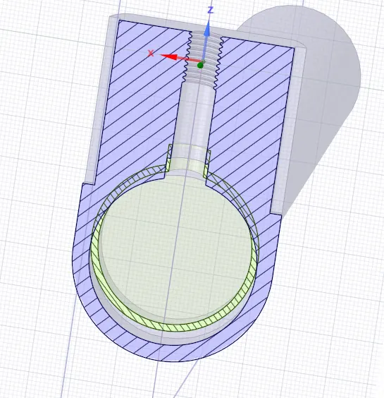
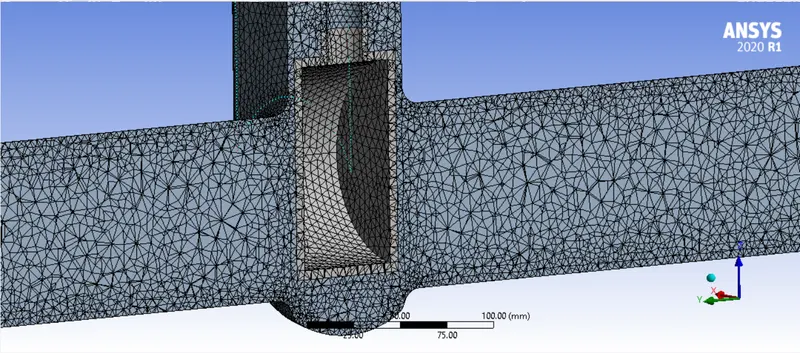
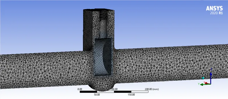
- We will supress all the other components except the internal volume and move to the meshing window.
MESHING:
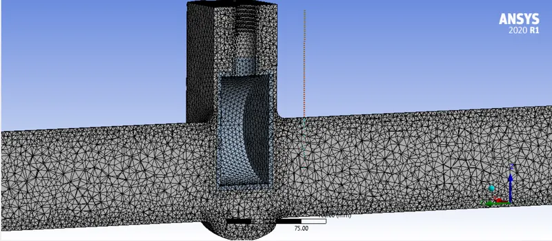
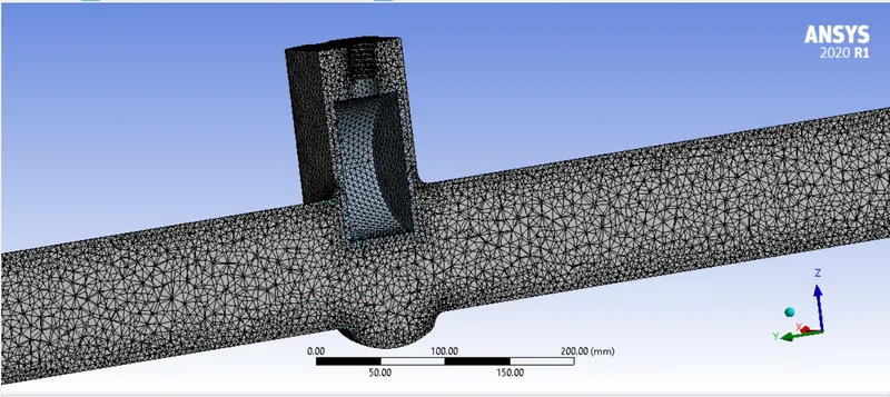
- Load the geometry in the meshing module
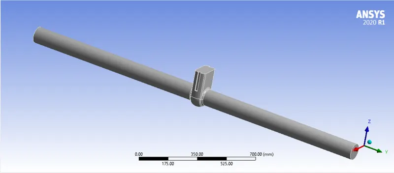
- After the geometry has been loaded, we will provide names selections to the inlet and outlet.
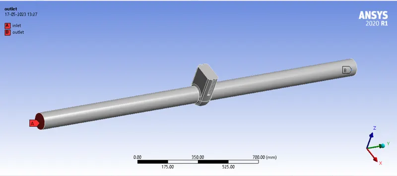
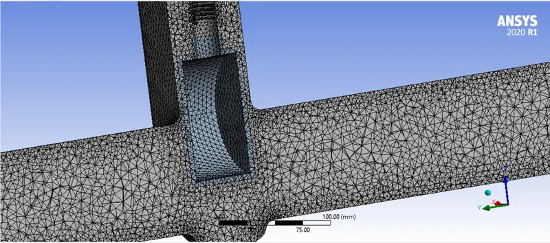
- As per the length of the fluid volume, a 5 mm mesh will be a good choice.
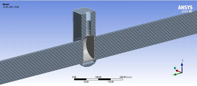
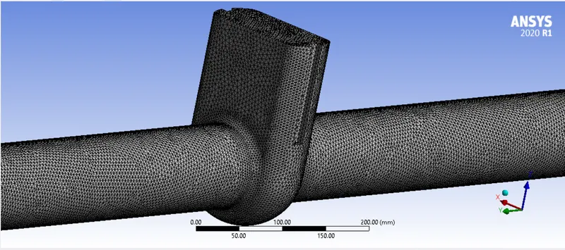
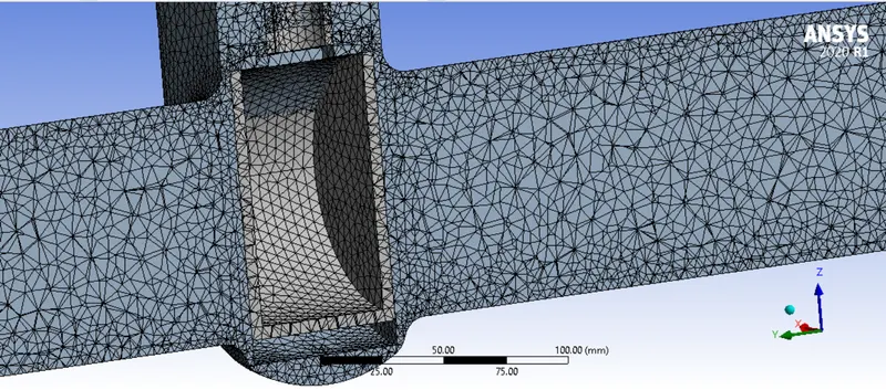
- We will update the mesh and move to the fluent window to perform calculations.
SOLVING:
Solver type:
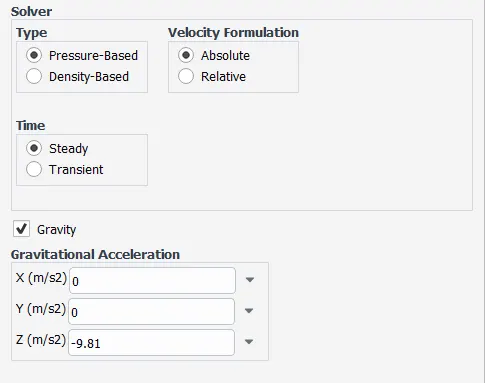
- We will be performing a pressure based steady state analysis.
- We will also specify gravity in the respective axis.
Material used:
- Since the fluid that flows in the pipe is waterr. We will import water from fluid database. We also need to change the material in the cell zone condition.
Boundary conditions:
- At the inlet, we will specify pressure inlet and specify a gauge pressure of 10 Pa.
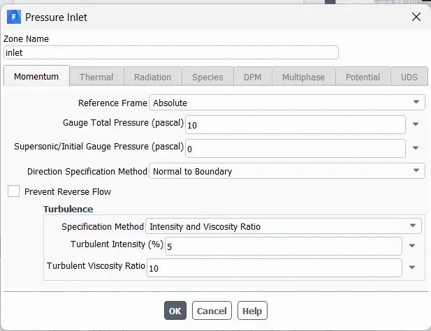
- The outlet will be kept as pressure outlet.
Model:
- Before selecting the model to be used. We need to evaluate whether the problem is in laminar or turbulent region.
- We will go to initialization tab and evaluate the velocity of flow.
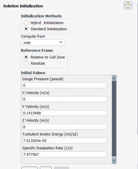
- The solution velocity comes out to be 0.14 m/s.
- Since we know the density, velocity and viscocity of the material being used, we can calculate the reynold's number.
`Re = (rho xx v xx D)/(mu)`
Here,
- `rho = 998 (kg)/m^3`
- `v = 0.14 m/s`
- `D = 0.1 m`
- `mu = 0.001003 (kg.m)/s`
Therefore, reynold's number = 13,930.
The reynold's number achieved is in the turbulent region. Hence, we will be using a turbulence model.
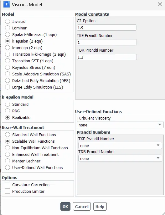
- To model the problem, we will be using K-epsilon model with realizable wall functions. We will also improve near-wall treatment by enabling scalable wall functions.
Plots and contour:
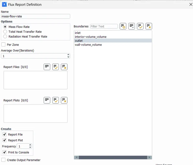
- In order to evaluate the mass flow rate at the outlet, we will create a flux report which will calculate mass flow rate at the outlet.
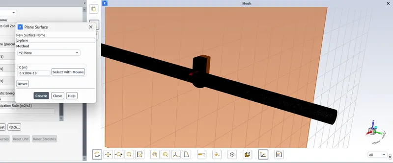
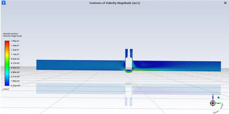
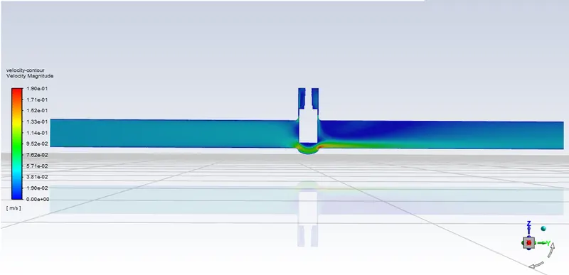
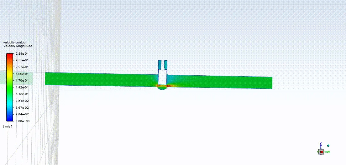
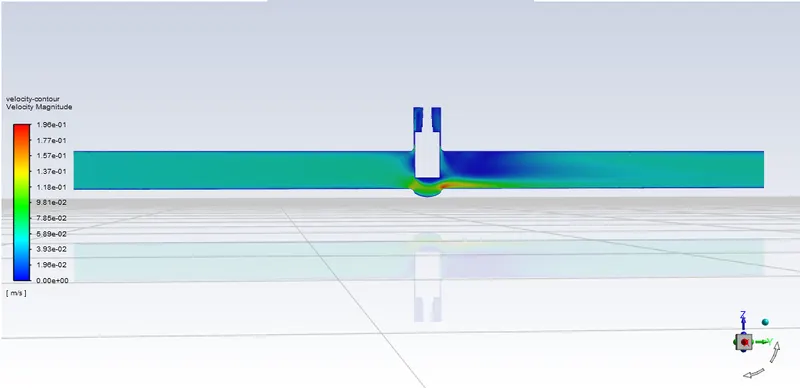
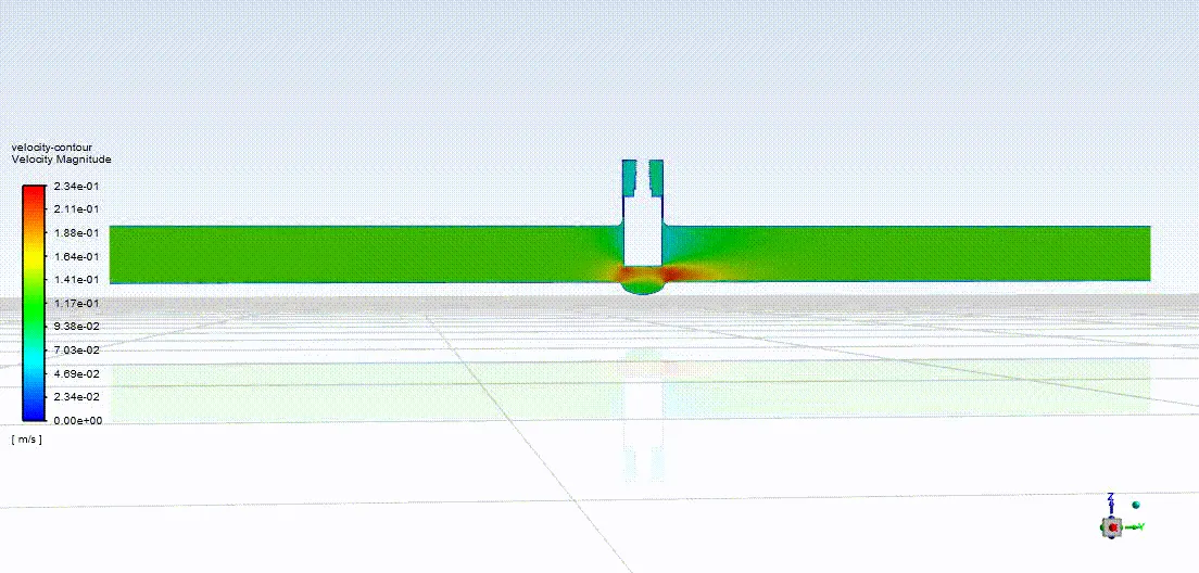
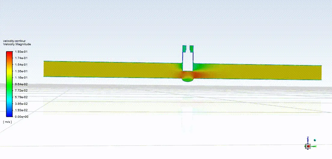
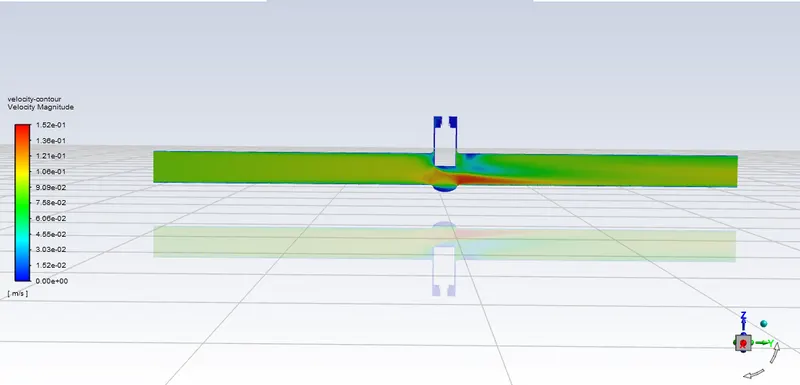
- We will also create a velocity contour which will help us visualise the flow. We will create this contour at a plane which is at the center of the geometry i.e., in YZ-plane.
- For that we need to define a plane.
- After creating velocity contour, we can move forward and run the calculation for 250 iterations.
Results (10% lift):
- Mass flow rate:
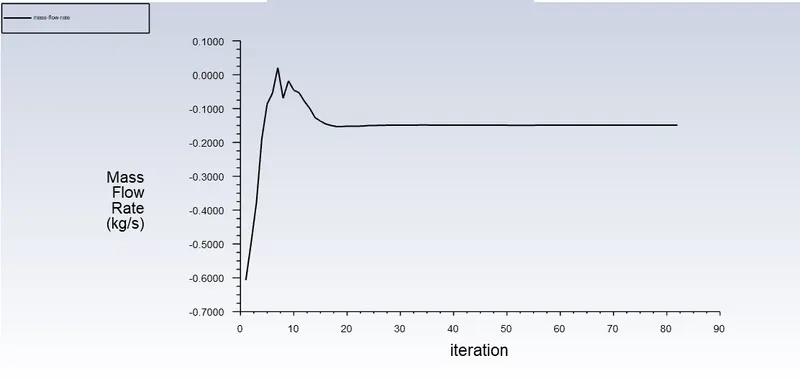
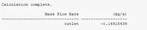
Note: Here, the negetive sign indicates the direction of flow which is outward. Hence, the negetive sign.
Make sure that the "print to parameter" has been checked in the mass flow rate report.
- Velocity contour:
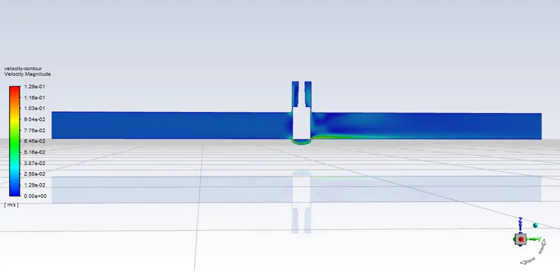
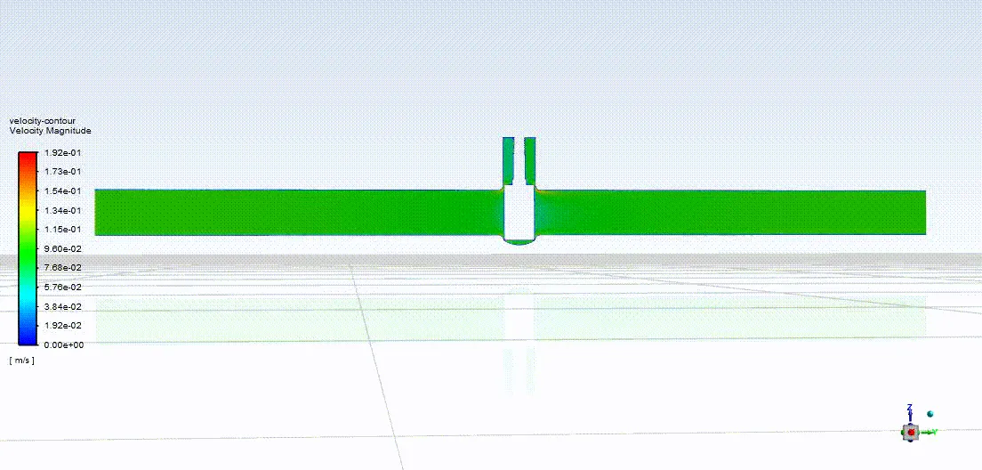
- Flow coefficients:
Flow coefficient `C_v = Q((S.G) / (triangleP) )^(1/2)`
Here,
`Q =`Mass flow rate = 0.149 kg/s
`S.G =`Specific gravity = 1
`triangle P =`Change in pressure = 10 Pa
Therefore,
`C_v = 0.149 (1/10)^(1/2)` = 0.046
- Flow factor:
Flow factor `K_v = 0.862 xx C_v`
Therefore,
`K_v = 0.862 xx0.046`= 0.039
Calculating flow parameters for different valve lifts:
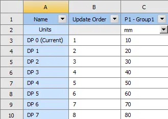
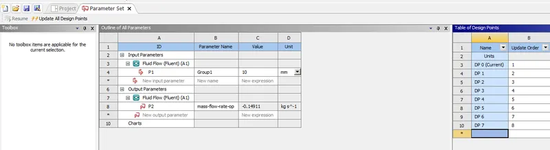
- While we were providing lift we parameterized the lift of gate disc. We can now open ANSYS workbench and open the "Parameter set".
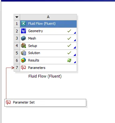
- In the right corner of the window, we can see a table.

- We can add our design data point here and perform calculation.
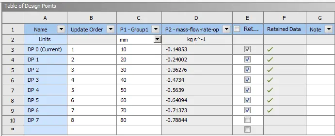
- When we click the update design data point button on top left corner, the solver evaluates the given quantity i.e., mass flow rate for all the design points.
RESULTS:
1. Lift = 20%
- Mass flow rate:

- Velocity contour:
- Flow coefficient:
Flow coefficient `C_v = Q((S.G) / (triangleP) )^(1/2)`
Here,
`Q =`Mass flow rate = 0.240 kg`
`S.G =`Specific gravity = 1
`triangle P =`Change in pressure = 10 Pa
Therefore,
`C_v = 0.240 (1/10)^(1/2)` = 0.0744`
- Flow factor:
Flow factor `K_v = 0.862 xx C_v`
Therefore,
`K_v = 0.862 xx0.0744`= 0.064`
2. Lift = 30%
- Mass flow rate:

- Velocity contour:
- Flow coefficient:
Flow coefficient `C_v = Q((S.G) / (triangleP) )^(1/2)`
Here,
`Q =`Mass flow rate = 0.36276 kg/s`
`S.G =`Specific gravity = 1
`triangle P =`Change in pressure = 10 Pa
Therefore,
`C_v = 0.36276 (1/10)^(1/2)` = 0.11471`
- Flow factor:
Flow factor `K_v = 0.862 xx C_v`
Therefore,
`K_v = 0.862 xx0.11471`= 0.0988`
3. Lift = 40%
- Mass flow rate:

- Velocity contour:
- Flow coefficient:
Flow coefficient `C_v = Q((S.G) / (triangleP) )^(1/2)`
Here,
`Q =`Mass flow rate = 0.4734 kg/s`
`S.G =`Specific gravity = 1
`triangle P =`Change in pressure = 10 Pa
Therefore,
`C_v = 0.4734 (1/10)^(1/2)` = 0.138318`
- Flow factor:
Flow factor `K_v = 0.862 xx C_v`
Therefore,
`K_v = 0.862 xx0.138318`= 0.119230`
4. Lift = 50%
- Mass flow rate:

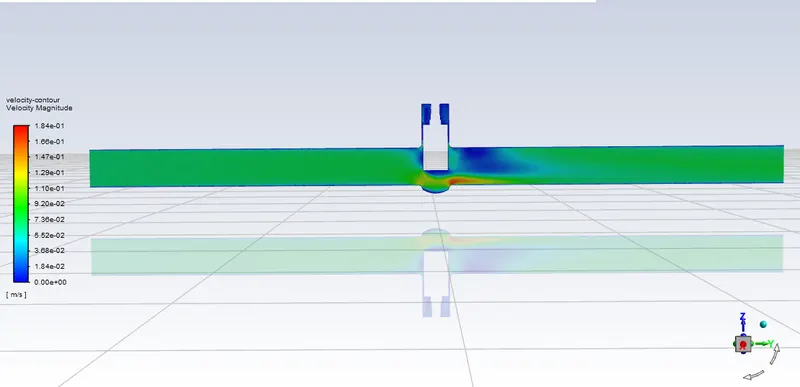
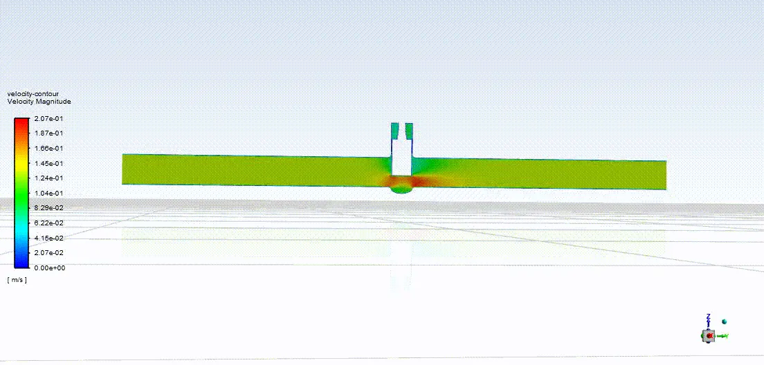
- Velocity contour:
- Flow coefficient:
Flow coefficient `C_v = Q((S.G) / (triangleP) )^(1/2)`
Here,
`Q =`Mass flow rate = 0.5639 kg/s`
`S.G =`Specific gravity = 1
`triangle P =`Change in pressure = 10 Pa
Therefore,
`C_v = 0.5639 (1/10)^(1/2)` = 0.17832`
- Flow factor:
Flow factor `K_v = 0.862 xx C_v`
Therefore,
`K_v = 0.862 xx0.17832`= 0.15371`
5. Lift = 60%
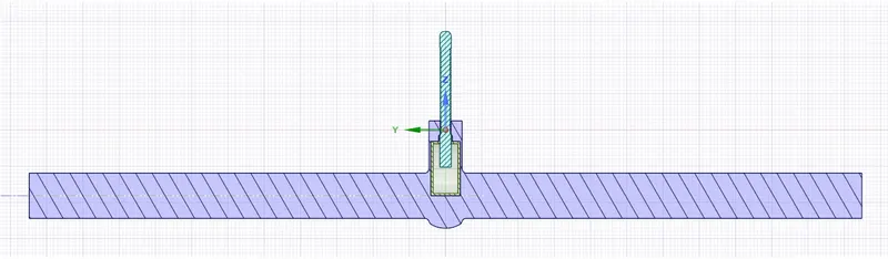
- Mass flow rate:

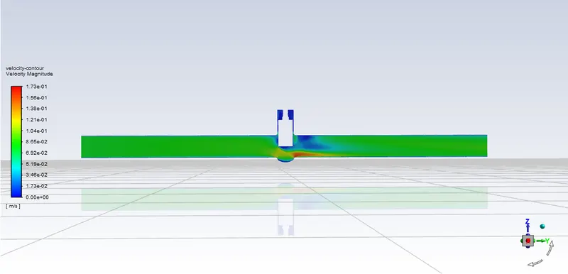
- Velocity contour:
- Flow coefficient:
Flow coefficient `C_v = Q((S.G) / (triangleP) )^(1/2)`
Here,
`Q =`Mass flow rate = 0.69094 kg/s`
`S.G =`Specific gravity = 1
`triangle P =`Change in pressure = 10 Pa
Therefore,
`C_v = 0.69094 (1/10)^(1/2)` = 0.21849`
- Flow factor:
Flow factor `K_v = 0.862 xx C_v`
Therefore,
`K_v = 0.862 xx0.21849`= 0.18833`
6. Lift = 70%
- Mass flow rate:

- Velocity contour:
- Flow coefficient:
Flow coefficient `C_v = Q((S.G) / (triangleP) )^(1/2)`
Here,
`Q =`Mass flow rate = 0.71597 kg/s`
`S.G =`Specific gravity = 1
`triangle P =`Change in pressure = 10 Pa
Therefore,
`C_v = 0.71597 (1/10)^(1/2)` = 0.226409`
- Flow factor:
Flow factor `K_v = 0.862 xx C_v`
Therefore,
`K_v = 0.862 xx0.22640`= 0.19515`
7. Lift = 80%
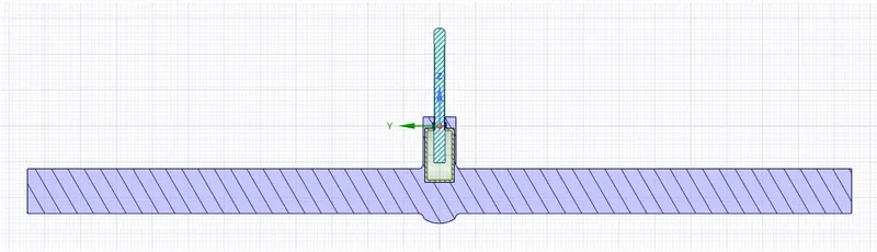
- Mass flow rate:

- Velocity contour:
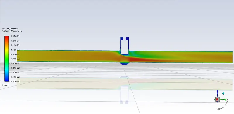
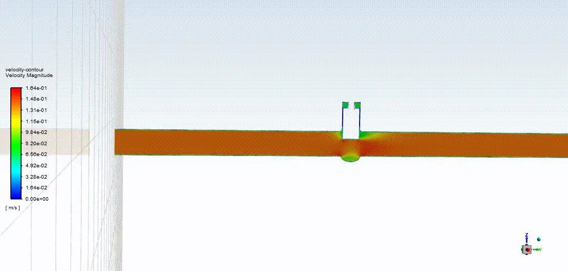
- Flow coefficient:
Flow coefficient `C_v = Q((S.G) / (triangleP) )^(1/2)`
Here,
`Q =`Mass flow rate = 0.78761 kg/s`
`S.G =`Specific gravity = 1
`triangle P =`Change in pressure = 10 Pa
Therefore,
`C_v = 0.78761 (1/10)^(1/2)` = 0.24906`
- Flow factor:
Flow factor `K_v = 0.862 xx C_v`
Therefore,
`K_v = 0.862 xx0.24906`= 0.21468`
RESULTS AND CONCLUSION:
| Sr No. | Lift % | Flow coefficient | Flow factor | Mass flow rate |
| 1. | 10 | 0.046 | 0.039 | -0.14915 |
| 2. | 20 | 0.0744 | 0.064 | -0.2400 |
| 3. | 30 | 0.11471 | 0.098 | -0.3627 |
| 4. | 40 | 0.13831 | 0.11920 | -0.4732 |
| 5. | 50 | 0.17832 | 0.15371 | -0.5655 |
| 6. | 60 | 0.21849 | 0.18833 | -0.6398 |
| 7. | 70 | 0.226409 | 0.19514 | -0.71597 |
| 8. | 80 | 0.24906 | 0.21468 | -0.7876 |
- Using a gate valve, we can achieve varying mass flow rate by increasing/decreasing the lift of gate disc.
- With a higher lift, we can get a higher mass flow rate with increase fluid velocity at the outlet.