Week 9 - Parametric study on Gate valve.
Introduction to GUI based CFD using ANSYS Fluent
Week 9 :- Parametric study on Gate valve
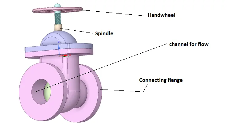
Gate valve is used for allowing the desired flow rate via channel, by lifting up the gate disc. It basically gets operated by handwheel.
Such valve is used for oil, gas, slurries, steam and corrosive liquids Tand are suitable for high pressure and temperature applications.
For the present case of parametric study, an already created 3-D CAD model of valve is loaded in Spaceclaim, it has following components.
Then to create a flow passage, the inner volume is extracted and the connecting flange length, (including the extracted volume) is elongated by 800 mm on both sides to create a flow passage.
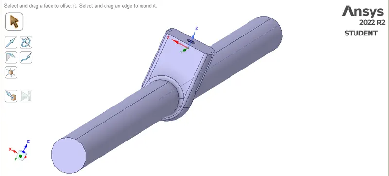
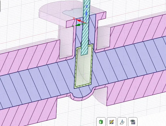
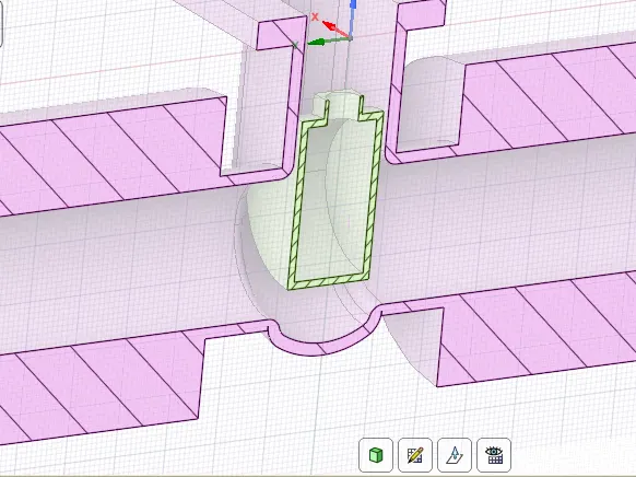
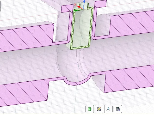
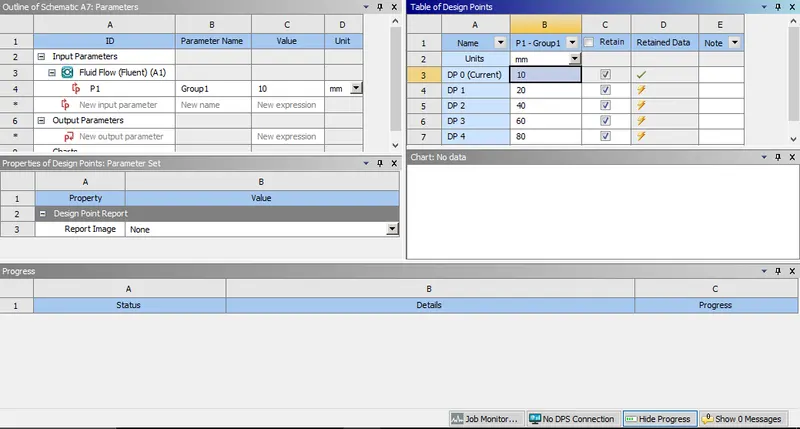
For the first case, the gate disc is lifted up by 10 mm, and a study group parameter is created.
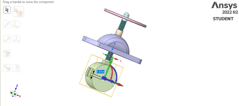
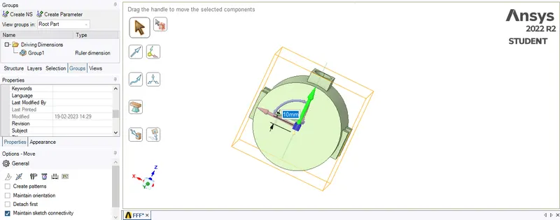
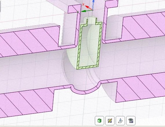
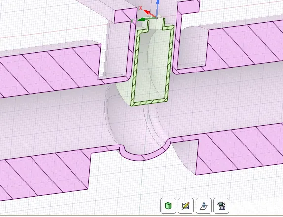
The cross sectional view, with the disc lifted by 10 mm is shown below:
Mesh:-
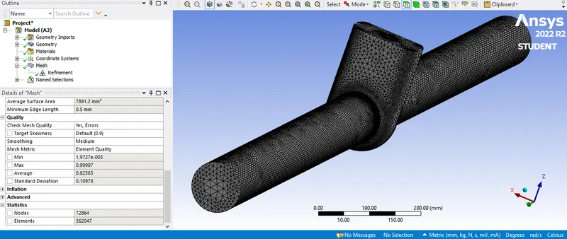
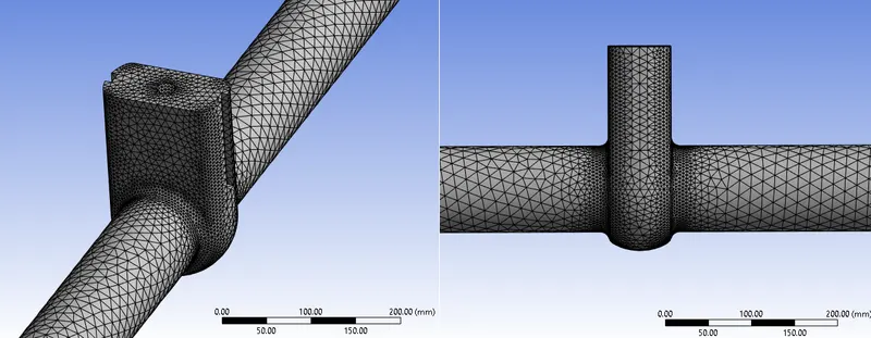
After giving the named selections, of inlet and outlet, the extracted fluid volume is discretized.
Fluent Setup:-
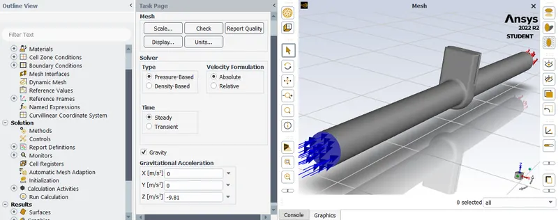
The Pressure Based solver is used to perform the steady state analysis of the flow, with the gravity acting in downwards direction.
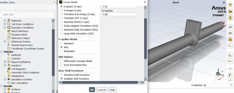
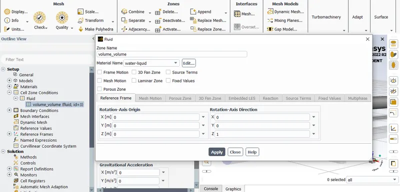
The viscous model is selected to k-epsilon RNG with scalable wall functions, and volume is assigned with fluid as water in Cell Zone conditions, which gives properties of water to the given selection of cell groups.
The boundary conditions are given as:
Inlet : Pressure Inlet, usually 10 Pa for pipe flows
Outlet : Pressure Outlet, 0 Pa.
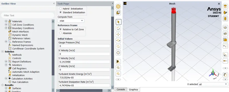
By computing values carried out from Standard initialization, the case is ran for cases having openings of gate disc from 10 % to 80 %.
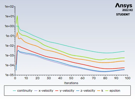
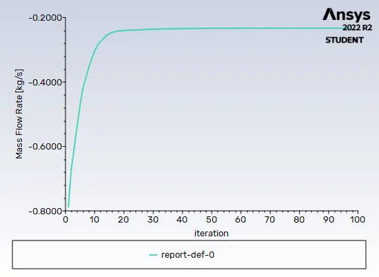
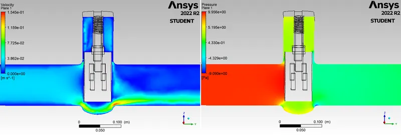
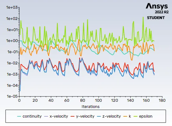
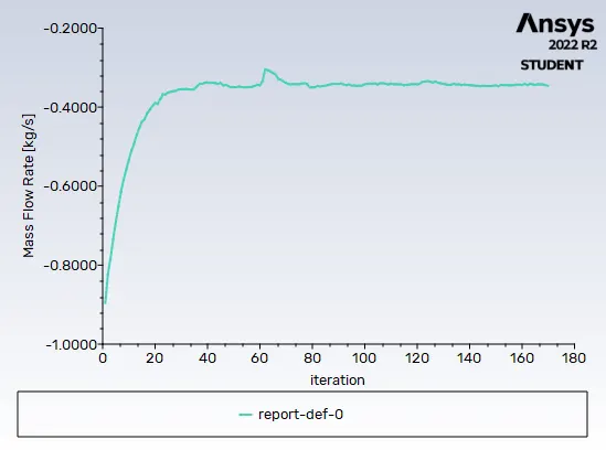
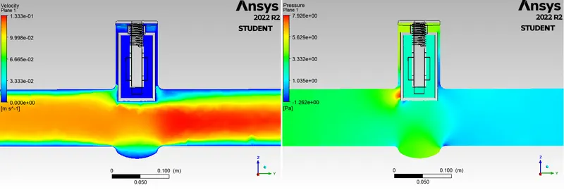
Cross-sections, residuals charts, mass flow rate chart and velocity contours for gate disc lifts:
For disc lift of 10 mm
For disc lift of 20 mm
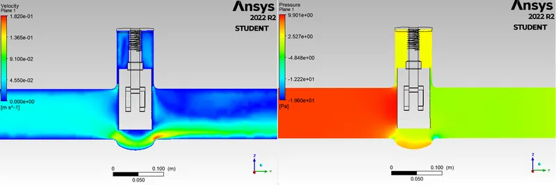
For disc lift of 40 mm
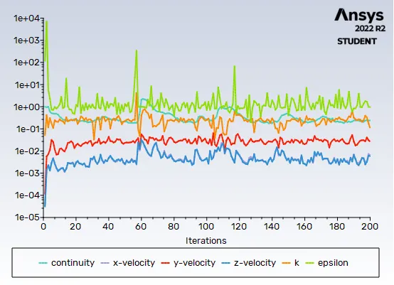
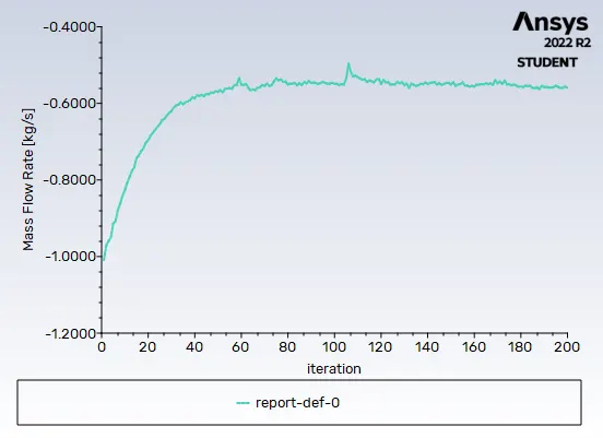
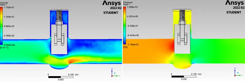
For disc lift of 60 mm
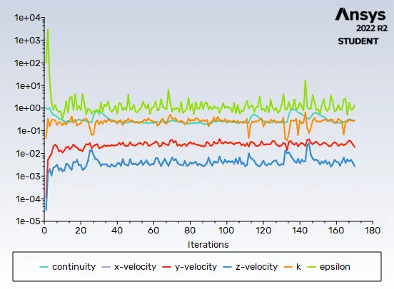
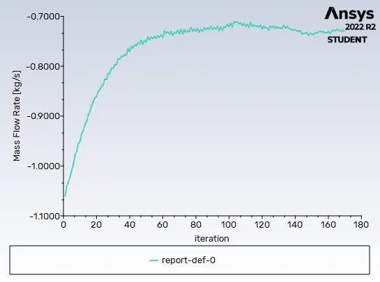
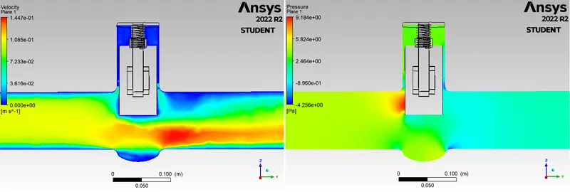
For disc lift of 80 mm
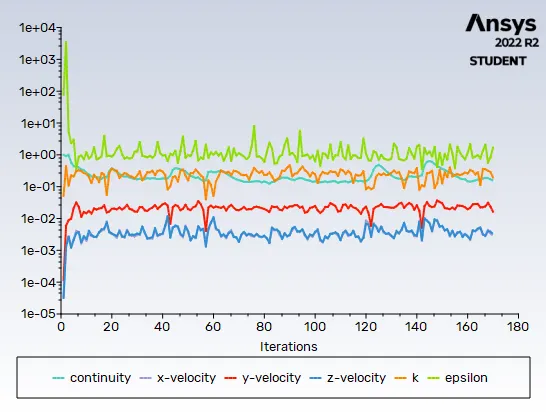
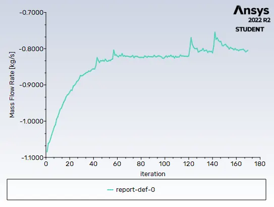
After creating the parameter study, following is noted:
The Flow Coefficient is the relative measure of efficiency, allowing the Fluid flow. It expresses the capacity and flow characteristic of a control valve It is calculated as;
`Cv = Q*sqrt((SG)/(ΔP))`
Q = Flow rate in gal/min
SG = specific gravity of water
ΔP = Pressure difference in psi
The Flow factor is given as;
`Kv = 0.865*Cv`
So,
| Disc lift (mm) | Inlet Pressure (Pascal) | Outlet Pressure (Pascal) |
Pressure drop (Pascal)/psi |
Mass flow rate (kg/s) |
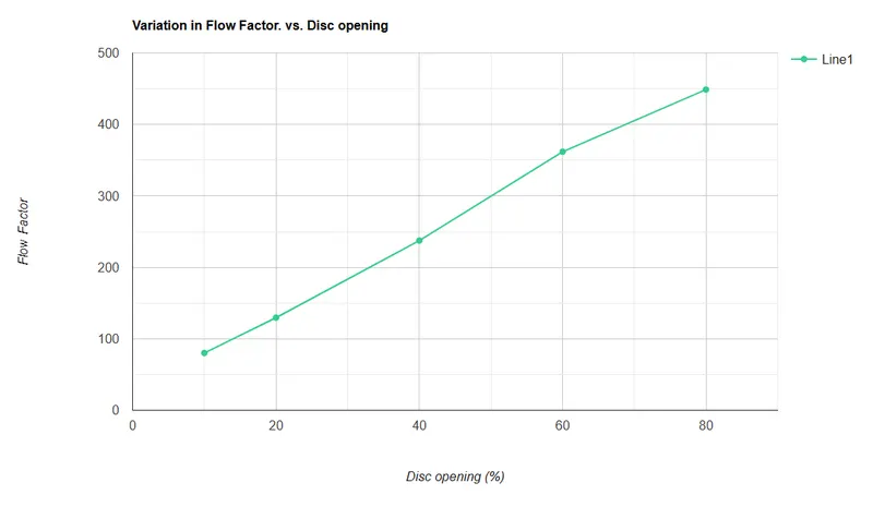
Flow Coeff. (`Cv`) | Flow Factor (`Kv`) |
| 10 | 10 | 0.46 | 9.54/ 0.00138 | 0.228 | 92.58 | 80.08 |
| 20 | 10 | 1.02 | 8.98/ 0.0013 | 0.341 | 149.76 | 129.54 |
| 40 | 10 | 2.64 | 7.36/ 0.00106 | 0.564 | 274.58 | 237.51 |
| 60 | 10 | 4.53 | 5.47/ 0.00079 | 0.742 | 418.40 | 361.91 |
| 80 | 10 | 5.86 | 4.14/ 0.0006 | 0.802 | 518.88 | 448.83 |
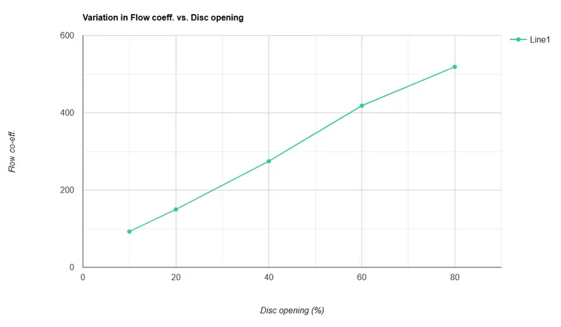
Graph Plots:
Conclusion:-
As seen from the previous table, with increase in the opening of the disc, the values of mass flow rate, flow coefficient and flow factor escalates.
It is also seen as the area for the flow is increased, via lifting the disc, the flow rate is higher. With gradual increase in the lift of disc, the pressure of water via flowing across that channel, shows less variation. In the first case, having much less passage of fluid to flow, thru the inlet, the pressure is quite high and when it flows via the narrow channel, pressure decreses and consequently the velocity increases, as the outlet pressure is much less. It follows Area Velocity principle in an incompressible flow regime.
Now, as the disc is lifted, fluid pressure is not that varying and pressure in the outlet gradually increases. This is because the water then passes thru the passage with larger area gradually.