Week 9 - Parametric study on Gate valve.
REPORT FOR CHALLENGE-9
Aim : To Perform a parametric study on the gate valve simulation by setting the opening from 10 % to 80% for to find the mass flow rate vatiation at outlet.
Software Required : Ansys Workbench – Fluid Flow vR2-2022
Hardware Required : Desktop, Keyboard, Mouse, CPU.
Theory:
A gate valve is a valve that opens by lifting a barrier (gate) out of the path of the fluid. Gate valves require very little space along the pipe axis and hardly restrict the flow of fluid when the gate is fully opened. The gate faces can be parallel but are most commonly wedge-shaped in order to be able to apply pressure on the sealing surface.
-
Gate Valve
-
Globe Valve
-
Check Valve
-
Plug valve
-
Ball Valve
-
Butterfly Valve
-
Needle Valve
-
Pinch Valve
-
Pressure Relief Valve
The flow coefficient of the device is a relative measures of its efficiency at allowing fluid flow. It describes the relationship between the pressure drop across anorifice valve and the corresponding mass flow rate.
Procedure :
Geometry:
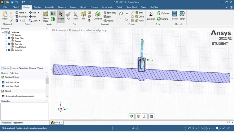
- Open space claim and import the given geometry.
- Now hide all the components except the spindle and gate disc.
- By using the box selection selected the both spindle and gate disk after selecting the move option.
- Then create a parameter set in the groups and assign the amount of value to move in upward direction.
- Create a body for the water flow with 800 mm.
- Then extract the volume by the selecting edge selection.
- Now surprise body for physics and close.
Meshing:
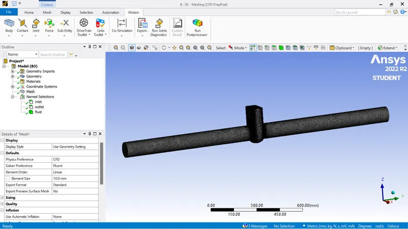
- Open the meshing.
- Give the element size as 10 mm and apply it on geometry.
- Set a program controlled inflation layer and update.
- Then assign the names as inlet, outlet and fluid then update and close.
Set-Up and Solving:
- Open the set up by choosing the requirements of your laptop for this allving process.
- Safety gravity in z direction with -9.81.
- Then open the viscous settings and set to K-Epsilon, realisable.
- Now open the materials manager and add the water as fluid from the database.
- Then I sign the water as fluid in the cell zone conditions.
- Now open the boundary conditions and set the inlet to pressure inlet and give pressure as 10pa.
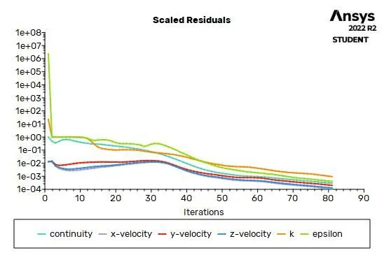
- Now create the definition residuals for the mass flow rate.
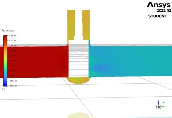
- Initialise and create the contours for the velocity and pressure and then give iterations and calculate.
Observations :
Geometry:
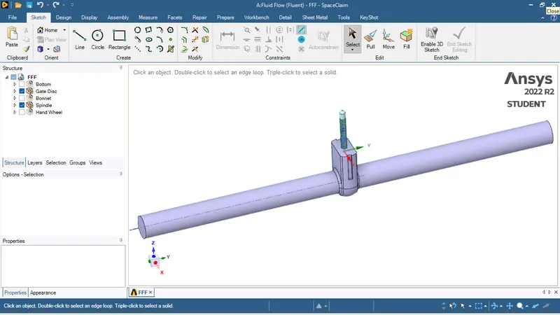
-For to analyze the flow rate change with respect to hight of the gate valve we changed the hight of the hate walve using parametric study and listed the analyzed caases.
| Case | Gate valve hight(mm) |
| 1 | 10 |
| 2 | 30 |
| 3 | 50 |
| 4 | 80 |
Case-1:
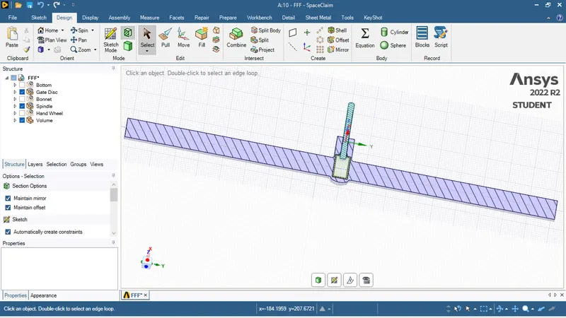
Case-2:
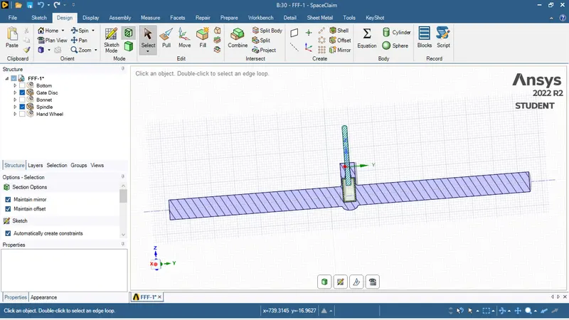
Case-3:
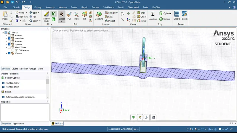
Case-4:
Mesh Details:
Material Settings:
- Fluid-Water
Viscous Model Settings:
- k-Epsilon
- Realizable
-The reason behind the using K epsilon Reliazable model is here the turbulence levels are higher due to the obstacle present in the fluid flow direction due to this there are chances of the formation of the eddy's thats why we choose in the change K epsilon turbulence model.
Boundary Conditions:
- Inlet-Pressure Inlet
Solution Status:
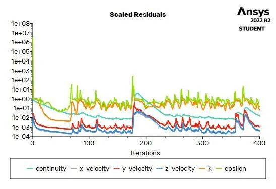
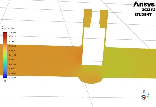
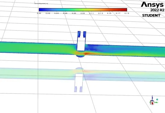
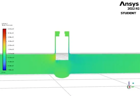
We did this analysis in 4 cases, to check how the flow rate is changing with respect to hight of the gate valve.
| Case | Gate valve hight(mm) |
| 1 | 10 |
| 2 | 30 |
| 3 | 50 |
| 4 | 80 |
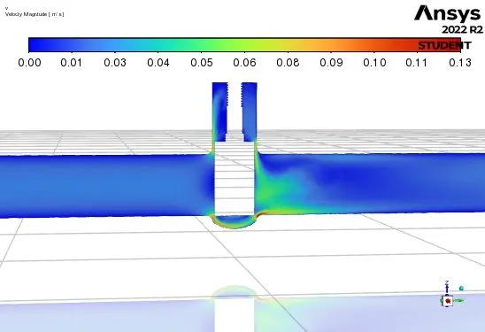
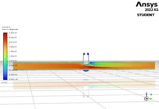
Case-1:
Plots and Contours:
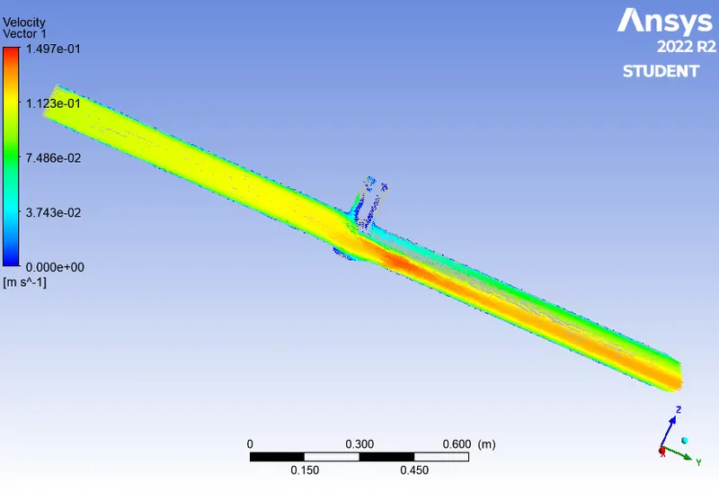
Case-2:
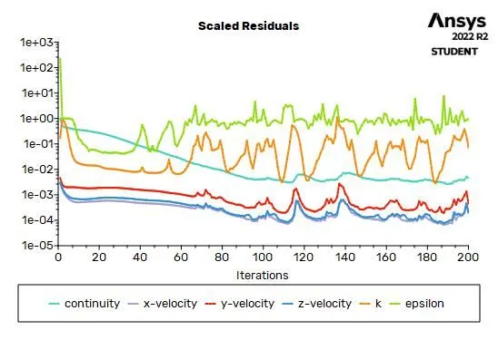
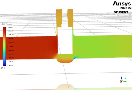
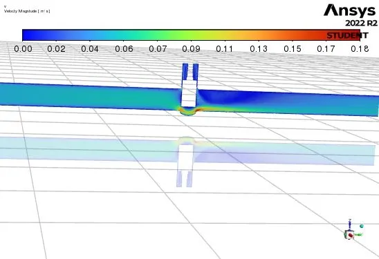
Plots and Contours:
Case-3:
Plots and Contours:
Case-4:
Plots and Contours:
Precautions :
1.Carefully solve the problem.
2.Choose the suitable methods carefully for to get the desired results.
3.Note the coordinates carefully.
Result:
| Gate Disk Hight(mm) | Mass Flow Rate at Outlet(m^3/s) | Outlet Velocity(m/s) |
| 10 | 0.1253 | 0..01838 |
| 30 | 0.3426 | 0.0440 |
| 50 | 0.5430 | 0.0710 |
| 80 | 1.7406 | 0.22 |
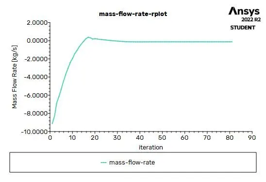
case-1:Mass Flow Rate graph at outlet for gate valve hight raised by 10mm.
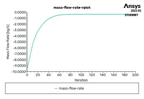
case-2:Mass Flow Rate graph at outlet for gate valve hight raised by 30mm.
case-3:Mass Flow Rate graph at outlet for gate valve hight raised by 50mm.
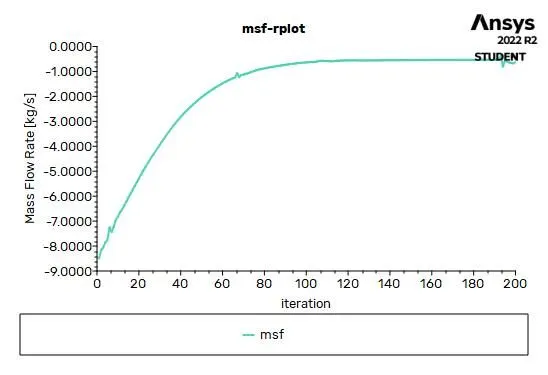
case-4:Mass Flow Rate graph at outlet for gate valve hight raised by 80mm.
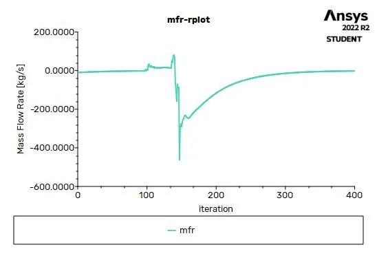
Conclusion:
As opening is increases, the flow rate of fluid increases.Here in this case we assumed the flow is entering with some pressure and the outlet pressure is less than the outlet.We can say that alone pressure has no effect on mass flow rate, it is the pressure difference created that affects the flow rate.
The value of pressure difference between the inlet section and outlet section affects the mass flow rate. If the pressure difference is more then the mass flow rate will be more and if the pressure difference will be less then the mass flow rate will be less.
Pressure is the amount of force exerted per unit area. For the same amount of force, if the area is smaller then value of pressure is more and if the area is more then the value of pressure is less.In this case the raise in the opening of the gate valve pressure is decreased.
Flow coefficient is directly promotional to the mass flow rate which means higher the mass flow rate, higher the flow coefficient and lower the pressure drop higher the mass flow rate.