Week 9 - Parametric study on Gate valve.
week 9:
parametric study on gate valve:
aim:
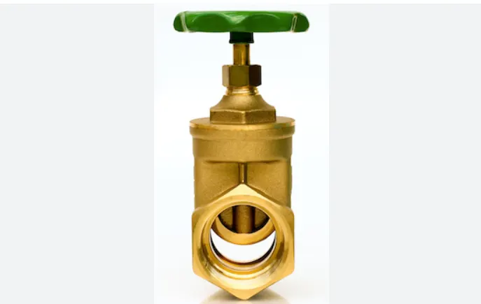
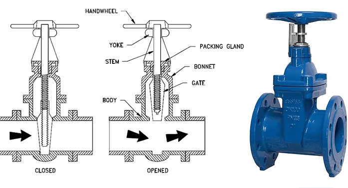
to simulate a gate valve in a ansys fluent and study the parametric on gate valve.
introduction:
• SpQcify jobname (this step is optional but recommended).
• Enter Preprocessor,
• Define element types and options.
• Define real constant for the element types (if the element type(s)
require real constants).
• Define material properties.
• Create the model:.
- Build solid model (using either top-down or bottom-up approach).
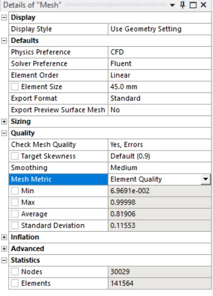
- Define meshing controls.
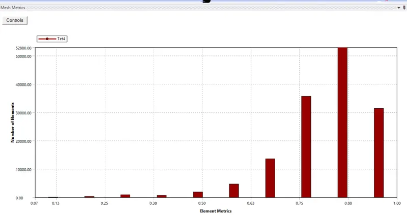
• Create the mesh.
• Exit the Preprocessor,
2. Boundary/Initial Conditions and Solution
• E nter Solution Processor,
• Define analysis type and analysis options.
• Specify boundary/initial conditions:
• Degree of freedom constraints.
- Nodal force loads.
• Surface loads.
• Body loads.
• I nertia loads.
• Initial conditions (if the analysis type is transient).
• Save database (this step is not required but is recommended).
• Initiate solution.
• Exit the Solution Processor,
3. Review Results
• Enter the appropriate Postprocessor (General Postprocessor or Time
History Postprocessor),
• Display results.
• List results.
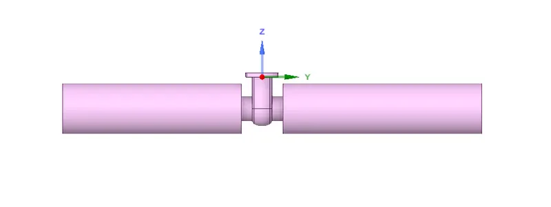

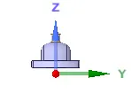
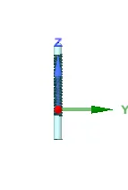
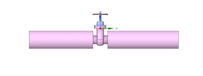
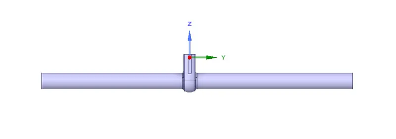
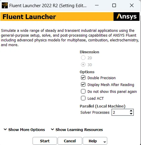
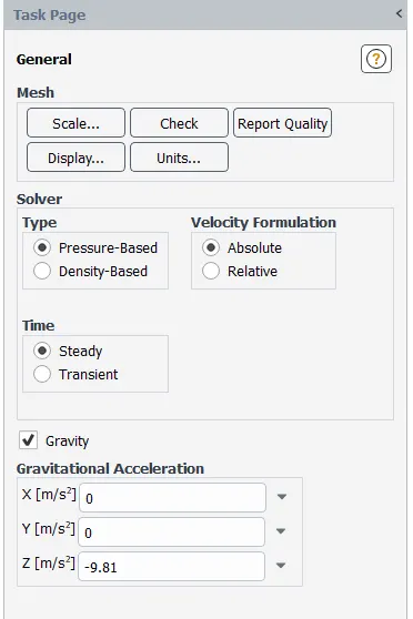
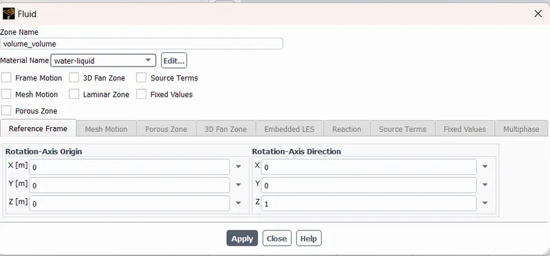
Steady-state, pressure-based solver with gravity enabled of value 9.81 m/s^2 in -ve z-direction.
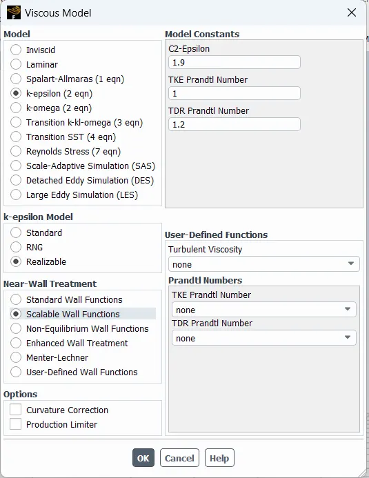
Viscous model: K-epsilon, Realizable with Scalable wall functions.
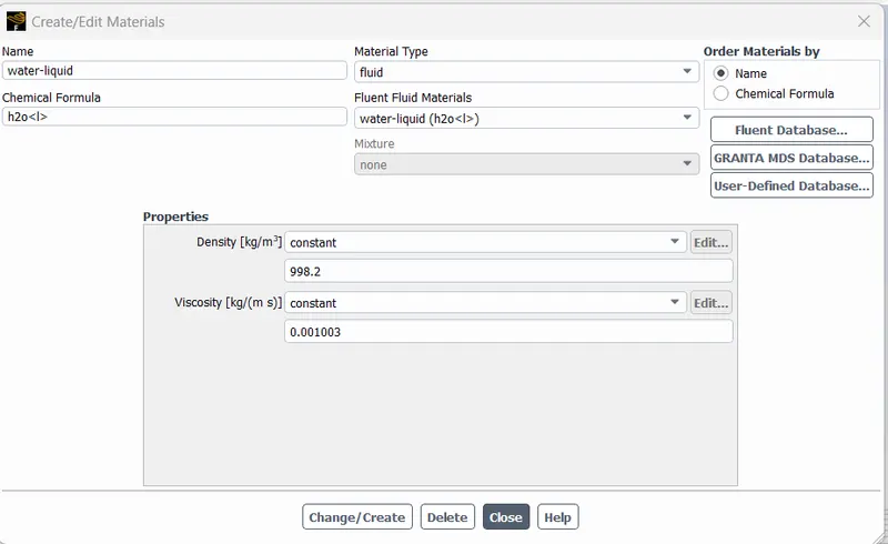
Material Properties: Water-liquid(H2O), Density:998.2 kg/m^3 , Viscosity:0.001003 kg/(m-s)
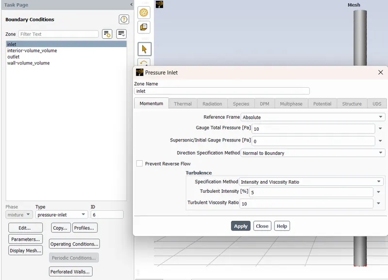
Boundary Conditions:
Inlet: Type= Pressure Inlet
Gauge Total Pressure = 10 Pa
Outlet: Type= Pressure Outlet
Gauge Total Pressure = 0 Pa
Wall: No-slip, stationary wall
Interior: Type= Interio
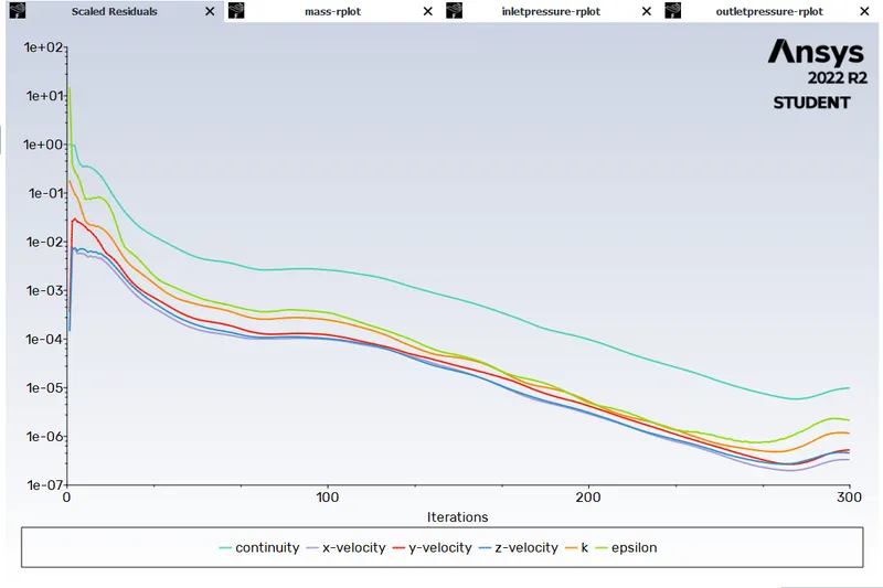
Residuals:
1. 10 mm opening
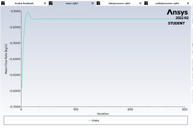
Mass flow rate:
1. 10 mm opening
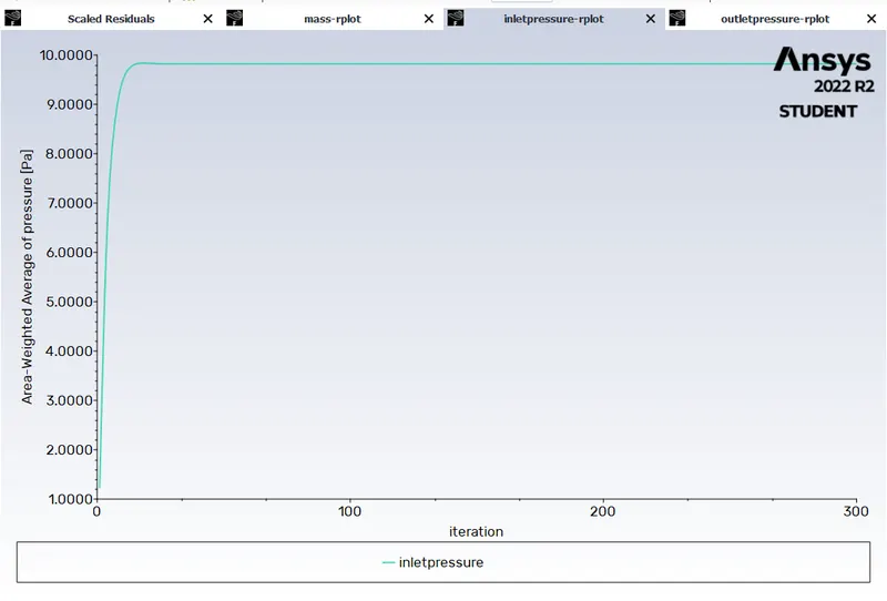
Differential Pressure:
1. 10 mm opening(before valve)
2. 10 mm opening(after valve) 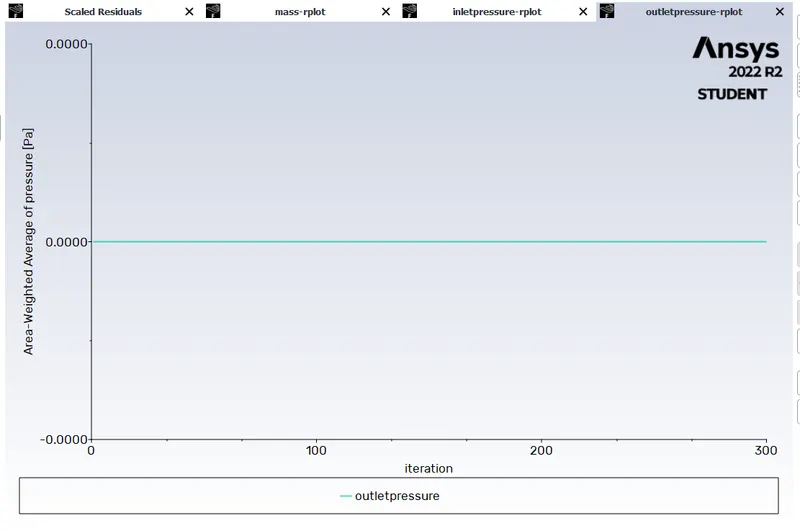
post processing:
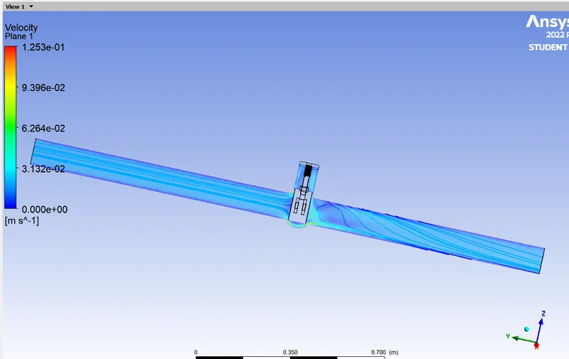
now we gor to results and create a velocity stream line for 10mm opening.
parameter:
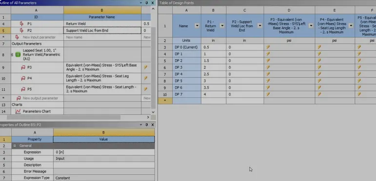
now click on pparameter.
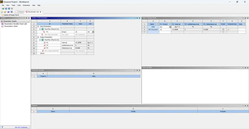
now create a data point and click on update.
it gives the value of mass flow rate , inlet pressure outlet pressure.
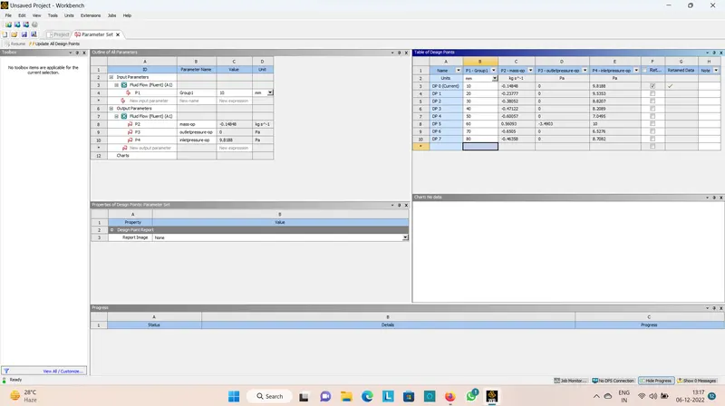
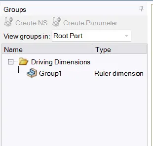
after completeing the update we have to set the dp.
for thet we have to right click on the data point we need and set to current.
go back to the geomentry, mash, setup and results all are updated to the set parameter value.
now calculating the flow coefficient and flow factor.
Valve Flow Coefficient (Cv) is a valve's capacity for a liquid or gas to flow through it. It is technically defined as “the volume of water at 60°F (in US gallons) that will flow through a valve per minute with a pressure drop of 1 psi across the valve.”
The gallons US per minute unit number 15.85 gal/min converts to 1 kg/sec

q=mass flow rate in gpm
p=pressure drop in psi.
for calculating flow factor.
calculation for 10mm opening.
a negative mass flow at a boundary means that mass is leaving your system, and a positive mass flow means that mass is entering your system.
q=0.14848 kg/s
Q=q*15.88
=0.14848*15.88
=2.357 gpm
specific gravity of water sg=1
Pressure drop, or pressure loss, is the difference in pressure as measured between two points in a pipe with flowing fluid. Δp = p1 - p2.
dp=9.8188 pa
DP=dp/6894.745
=9.8188/6894.745
=0.00142 psi
cv=q*sqrt(sg/dp)
=2.357*sqrt(1/0.00142)
=62.548
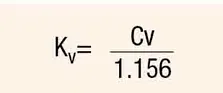
kv=cv/1.156=>62.548/1.156
=53.761 m^3.h^-1
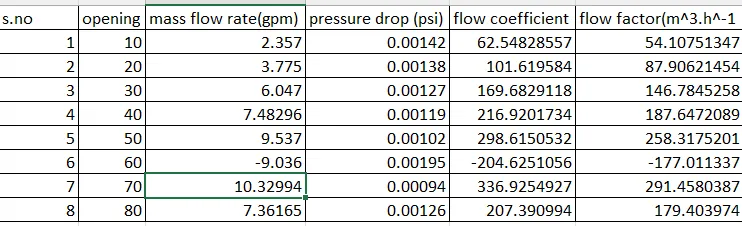
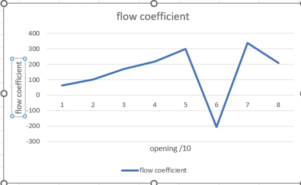
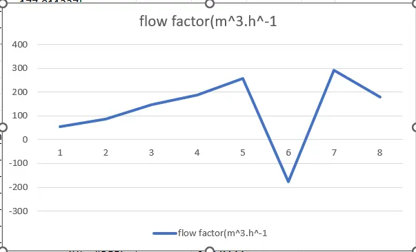
from the above calculation calculate all the value and plot a graph in excel.
graph of flow coefficient:
flow factor:
the workbench gate valve system is attached.
Conclusion:
1. Flow-coefficient and flow-factor increases with increasing opening percentage and decrease on 60% and again increses.
2. Differential pressure across the gate valve decreases with increasing opening percentage. This is because there is less blockage to the flow.
3. Mass-flow rate and velocity increases with increasing opening percentage. This is because there is more pathway for the water to flow.
4. Gate valve should operate in a fully-opened or fully-closed position. A partially-opened valve induces vibration which can damage the gate valve.
5. Also the gate valve should be closed gradually rather than suddenly, as it causes a water hammer effect which can again damage the gate valve.