Week 9 - Parametric study on Gate valve.
Aim:
For this challenge, you will have to perform a parametric study on the gate valve simulation by setting the opening from 10 % to 80%.
Objectives:
- Obtain the mass flow rates at the outlet for each design point.
- Calculate the flow coefficient and flow factor for each opening and plot the graph.
- Discuss the results of the mass flow rate and flow coefficient.
Introduction:
Gate valve:
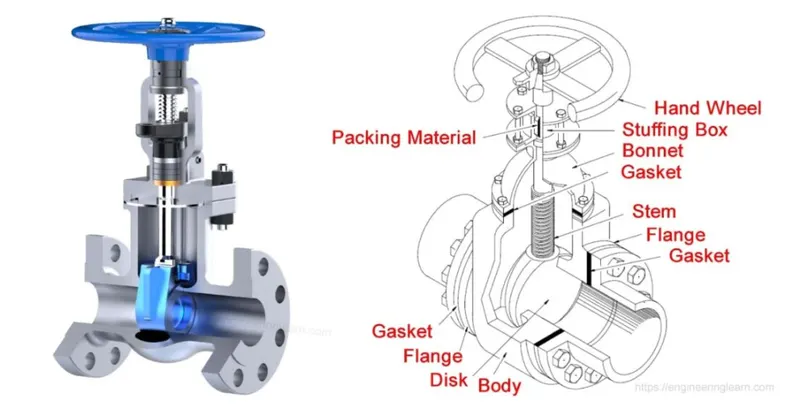
A gate valve, also known as a sluice valve, is a valve that opens by lifting a barrier (gate) out of the path of the fluid. Gate valves require very little space along the pipe axis and hardly restrict the flow of fluid when the gate is fully opened. The gate faces can be parallel but are most commonly wedge-shaped (in order to be able to apply pressure on the sealing surface).
Use:
Gate valves are used to shut off the flow of liquids rather than for flow regulation. When fully open, the typical gate valve has no obstruction in the flow path, resulting in very low flow resistance. The size of the open flow path generally varies in a nonlinear manner as the gate is moved. This means that the flow rate does not change evenly with stem travel. Depending on the construction, a partially open gate can vibrate from the fluid flow.
Gate valves are mostly used with larger pipe diameters (from 2" to the largest pipelines) since they are less complex to construct than other types of valves in large sizes.
At high pressures, friction can become a problem. As the gate is pushed against its guiding rail by the pressure of the medium, it becomes harder to operate the valve. Large gate valves are sometimes fitted with a bypass controlled by a smaller valve to be able to reduce the pressure before operating the gate valve itself.
Gate valves without an extra sealing ring on the gate or the seat are used in applications where minor leaking of the valve is not an issue, such as heating circuits or sewer pipes.
Gate valves are typically constructed from cast iron, cast carbon steel, ductile iron, gun metal, stainless steel, alloy steels, and forged steels.
The flow coefficient - Cv - or the flow factor - Kv - are commonly used to specify capacities of control valves.
Application of gate valve:
A typical gate valve application includes
- Cooling water systems.
- Fuel oil systems.
- Feedwater or chemical feed system.
- Boiler and main steam vents and drains.
- Turbine lube oil system.
Case 1: Gate valve opening 10mm
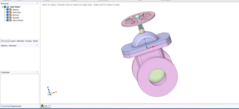
Opening model in spaceclaim
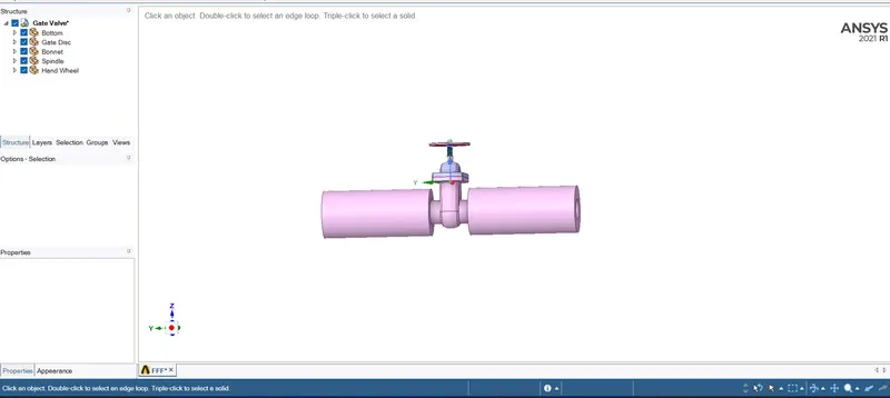
Pulled into two sides so that we can see pressure and velocity contours more clearly
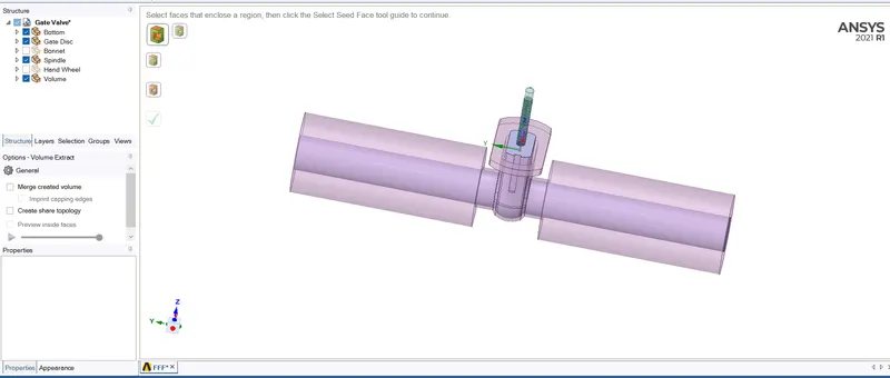
Volume extraction done
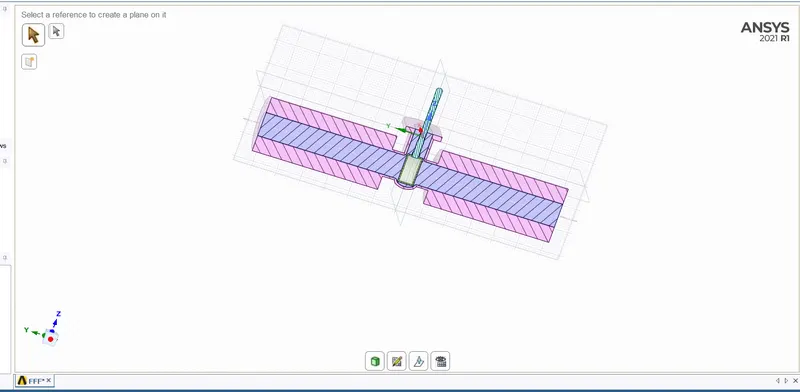
Showing cutsection view after volume extraction of fluid
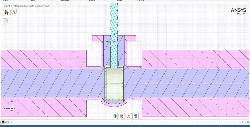
Figure shows disc is at completed closed position now.
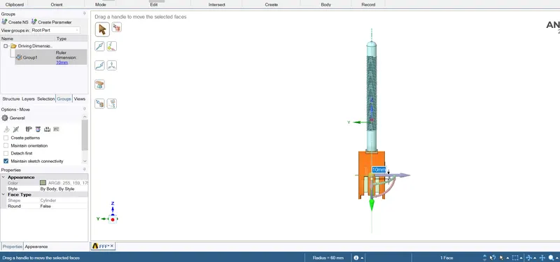
Disc moved to 10mm distance upwards
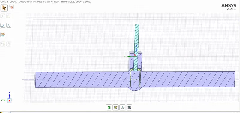
10mm distance moved in upward direction
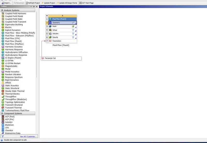
Parameter set created
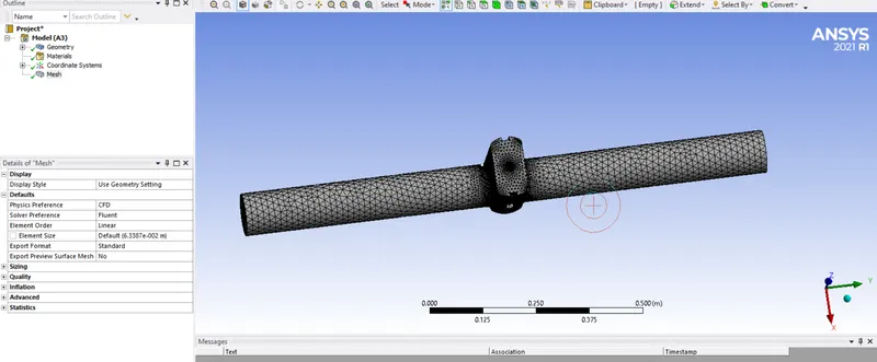
Meshing done with default meshsize 63mm
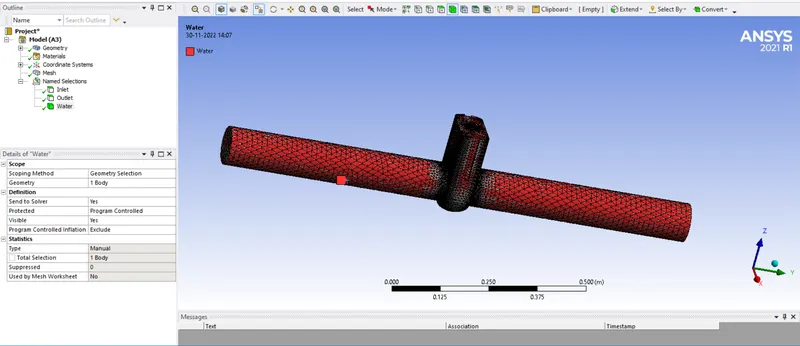
Naming given
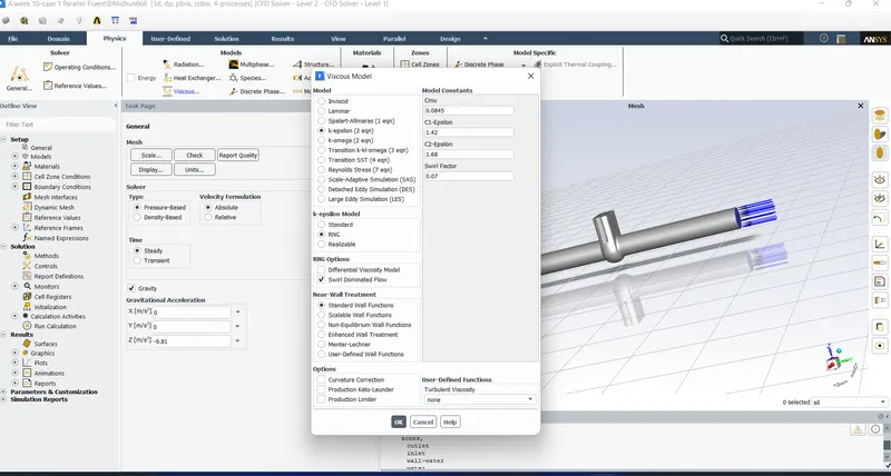
Turbulence model and gravity giving
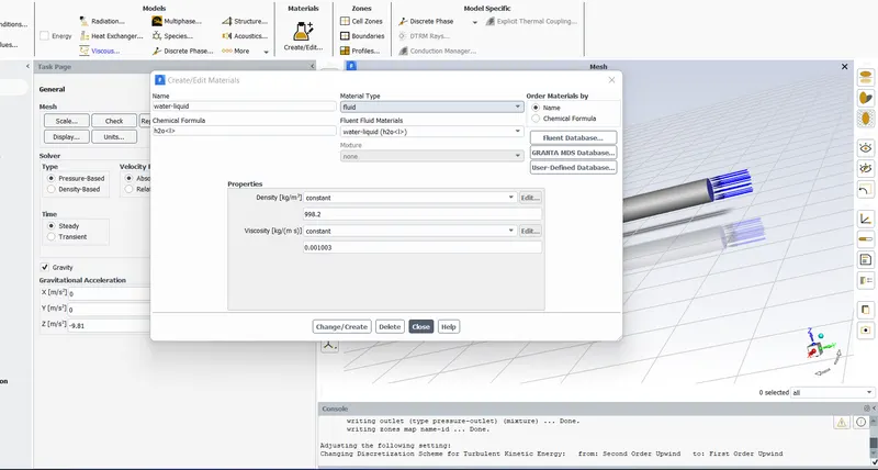
Adding material
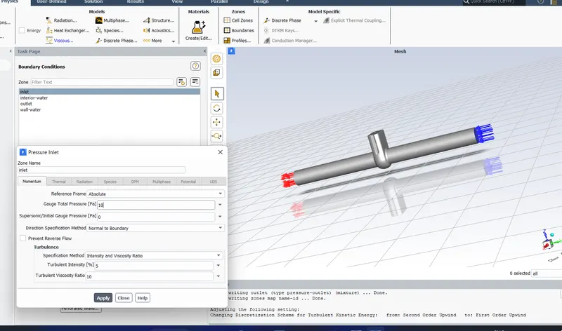
Giving inlet pressure as 10Pa
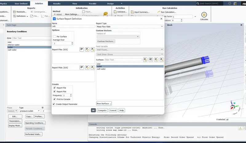
Creating surface report for mass flow rate
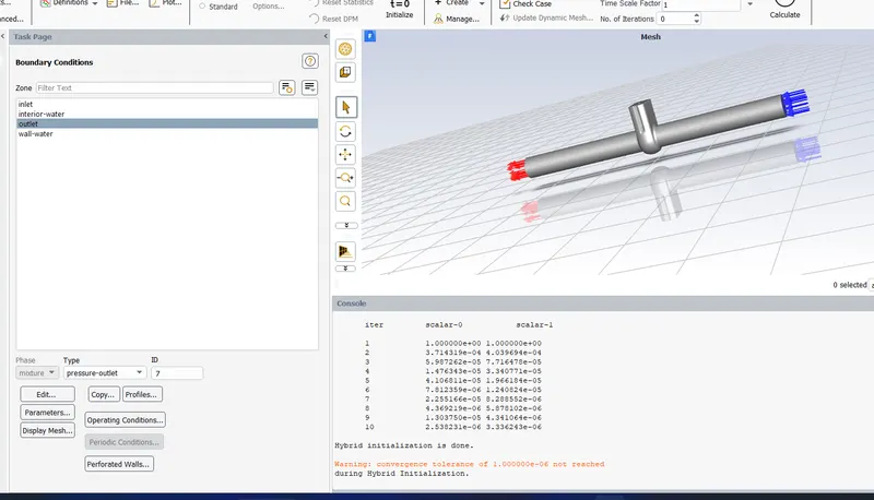
Hybrid Initialization done
RESULTS AND DISCUSSIONS:
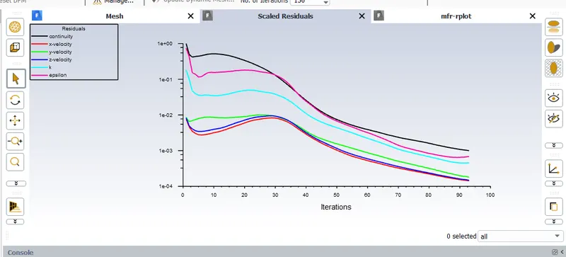
Showing scaled residuals
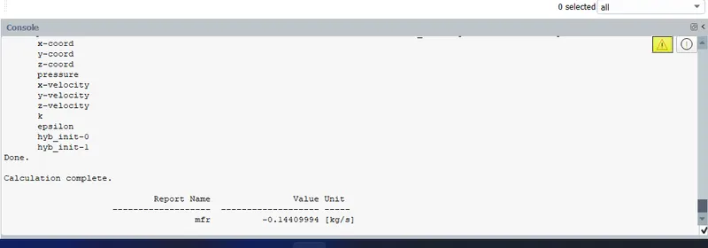
Showing mass flow rate as 0.144 kg/sec.(Negative sign indicates that mass flow is exitting at outlet)
So, here the volume flow rate is = 0.144/1000=0.000144m3/sec
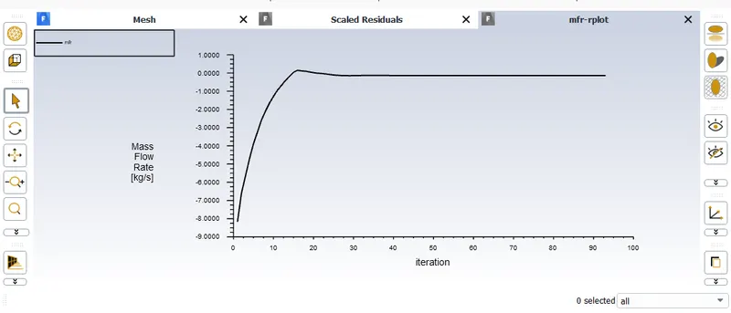
Mass flow rate plot
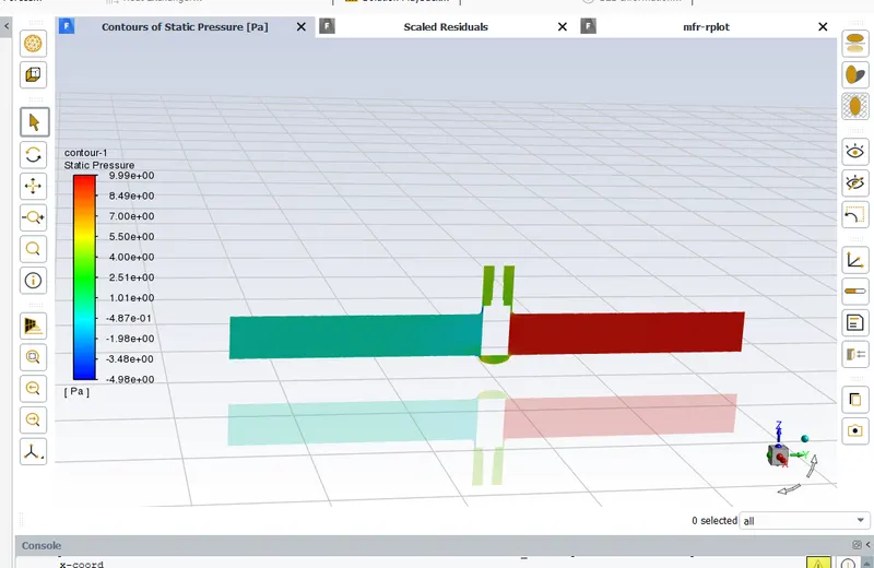
Contour of static pressure
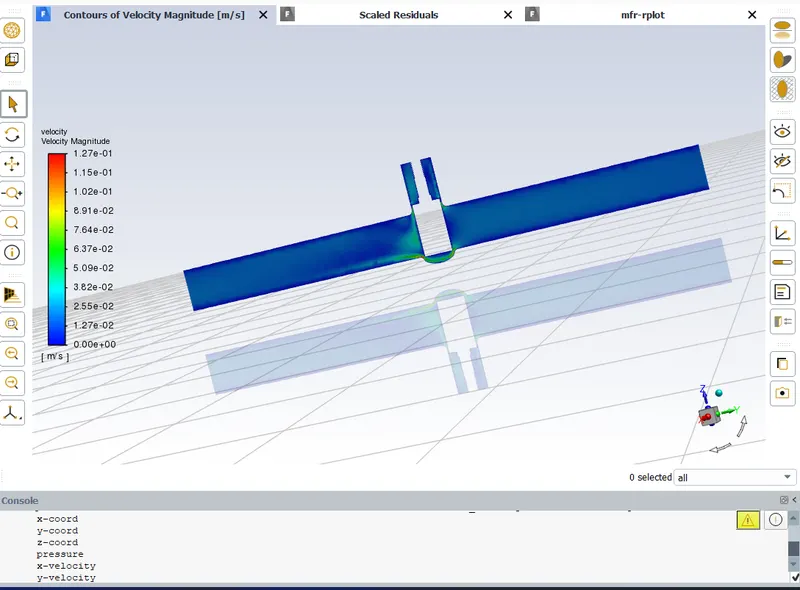
Contour of velocity
It is clear that velocity is increasing near gate valve due to reduction in area
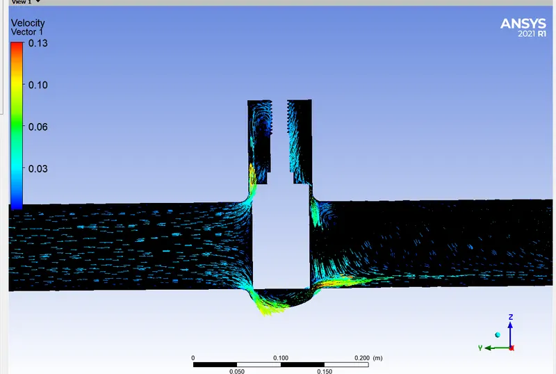
Showing velocity vector
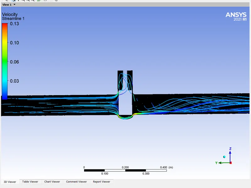
Showing velocity streamlines
Note: Video for this case uploaded below.
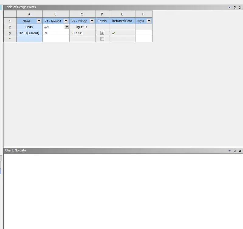
In parametric set we can see the mass flow rate
Case 2: 20mm gate lift.
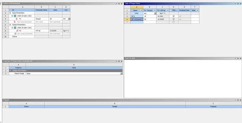
Here mass flow rate got as -0.233kg/sec
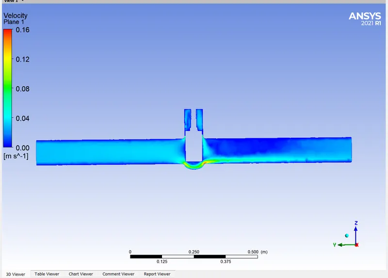
Showing velocity contour
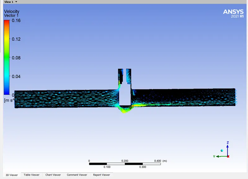
Showing velocity vector
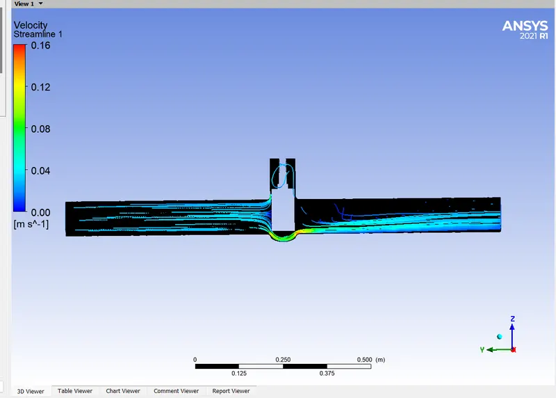
Showing streamlines
Note: Video for this case uploaded below
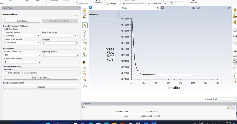
Mass flow rate plot
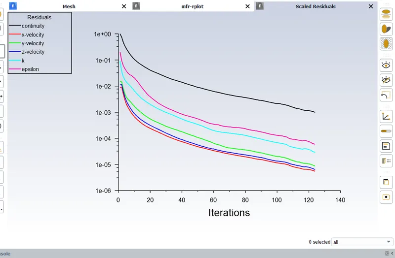
Residual plot
Case 3: 30mm gate lift
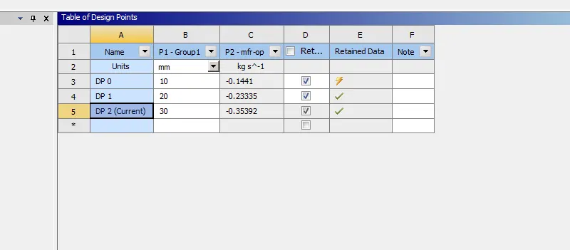
Showing mass flow rate got as -0.35392kg/sec
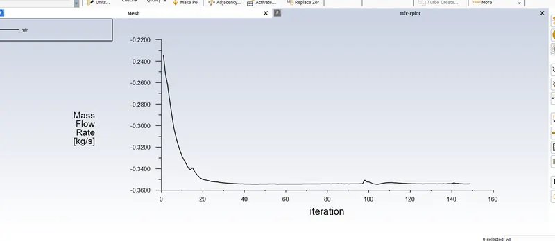
Plot of mass flow rate
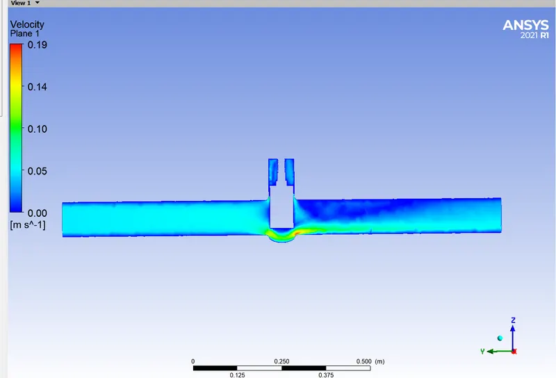
Showing velocity contour
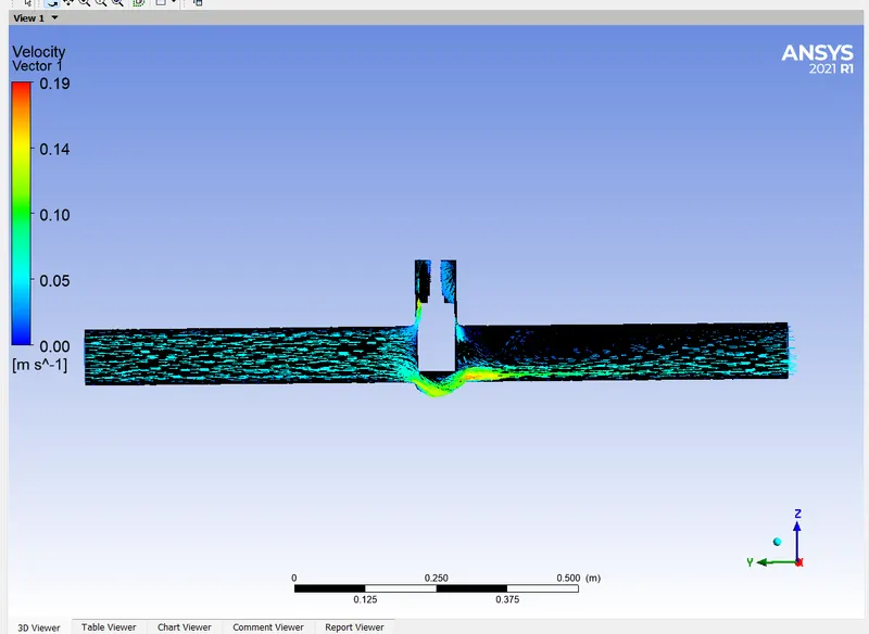
Showing velocity vector
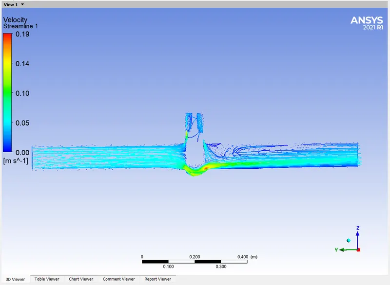
Showing streamlines
Note: Video for this case uploaded below
Case 4: 40mm lift
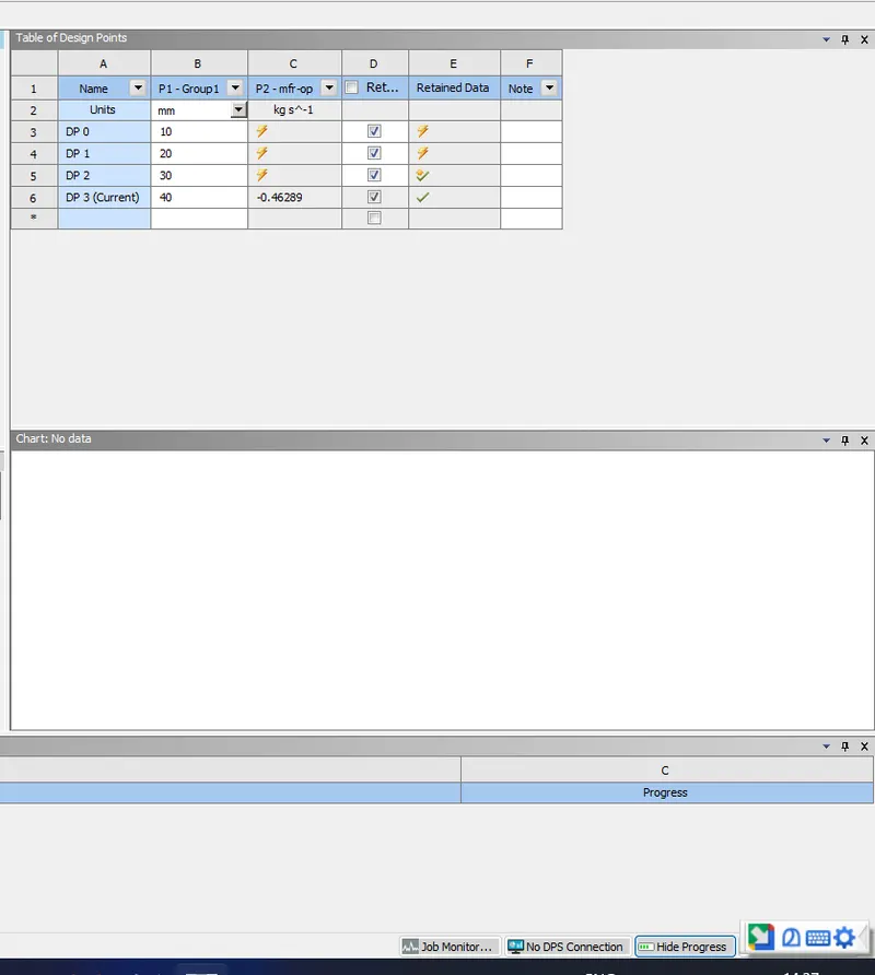
Showing mass flow rate as -0.46289 kg/sec
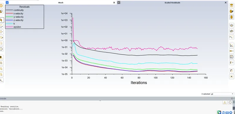
Showing residuals
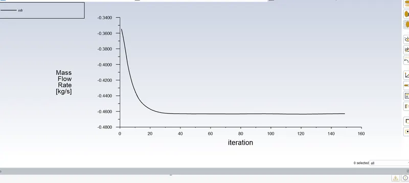
Plot for mass flow rate
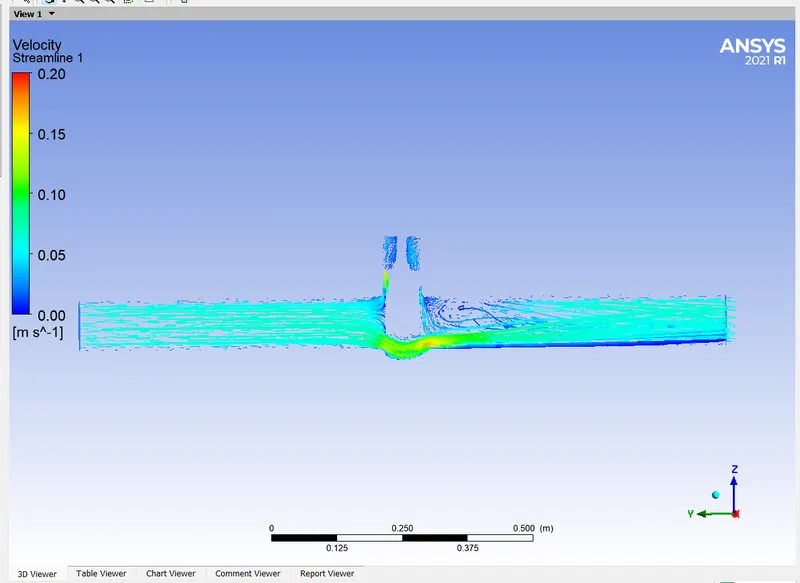
Streamlines
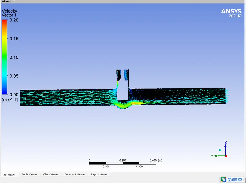
Velocity vector
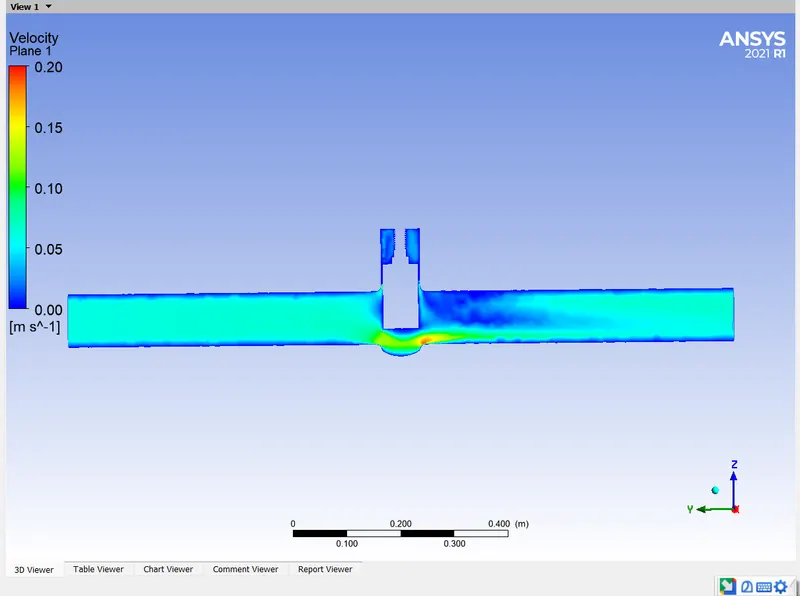
Velocity contour
Note: Video uploaded below
Case 5: 50 mm gate lift
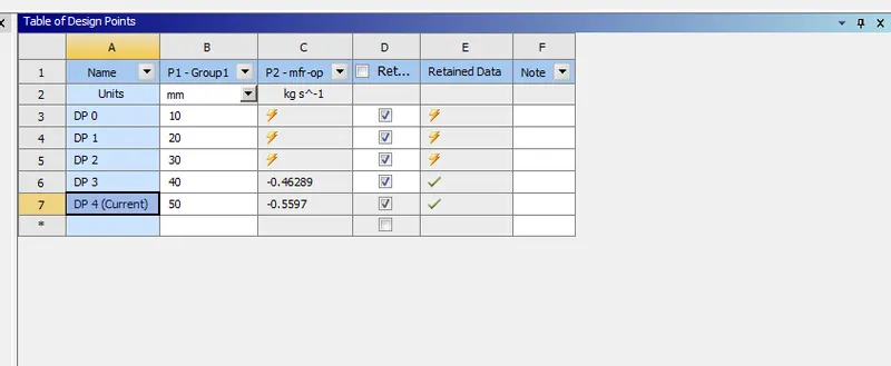
Showing mass flow rate as -0.5597kg/sec
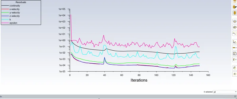
Residulas
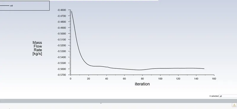
mass flow rate plot
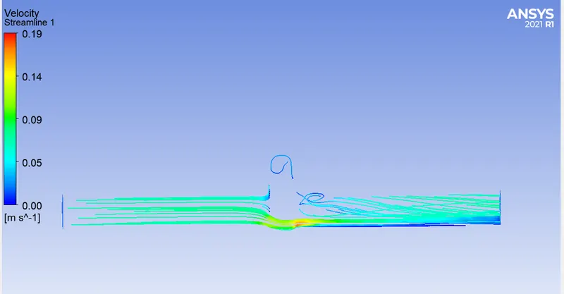
Streamlines
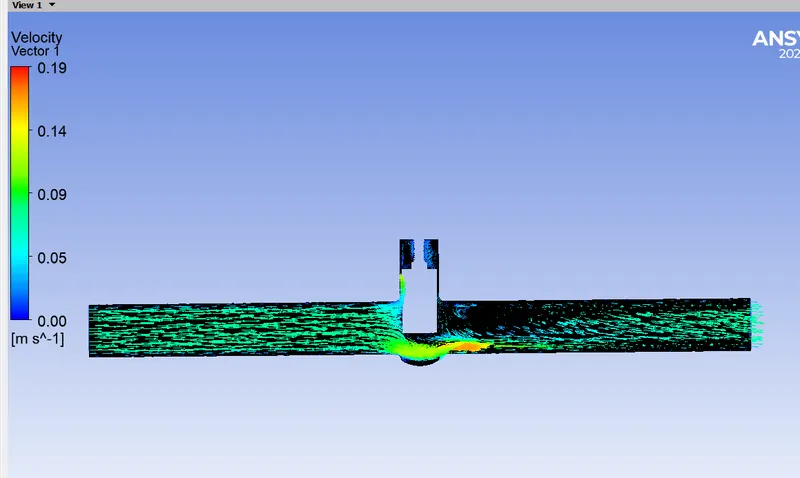
Velocity vector
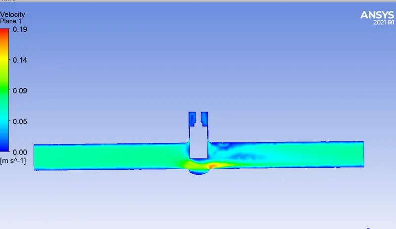
Velocity contour
Note: Video uploaded below
Case 6: 60mm gate lift
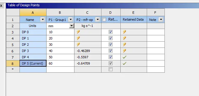
Showing mass flow rate as -0.64709 kg/sec
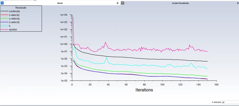
Residuals
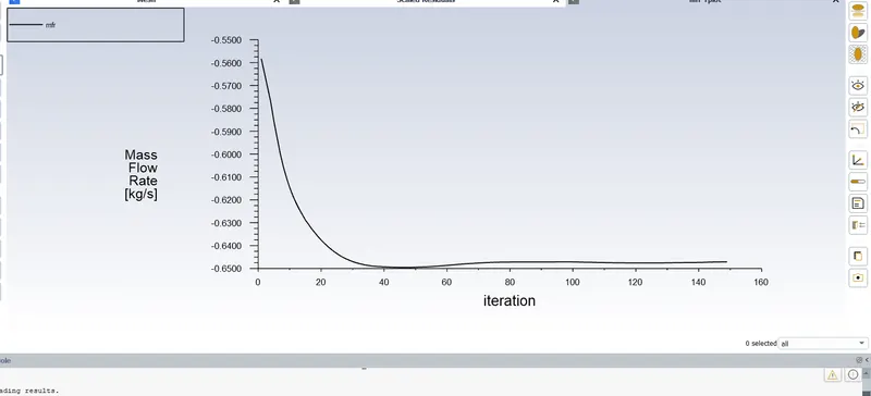
Mass flow rate plot
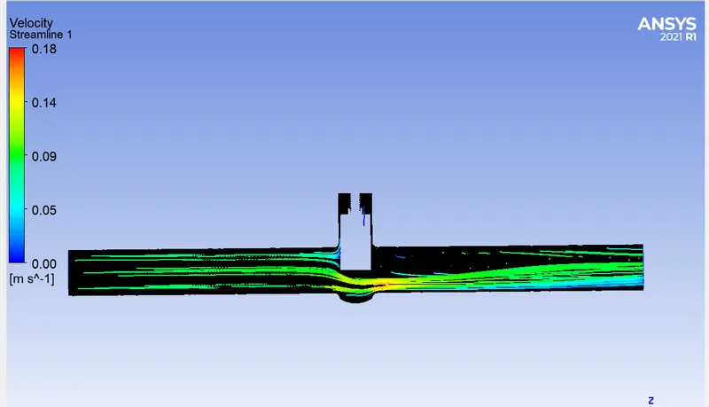
Streamlines
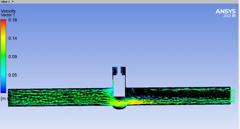
Velocity vector
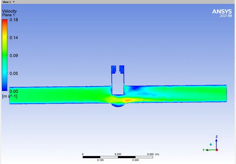
Velocity contour
Note: Vide uploaded below
Case 7: 70 mm gate lift
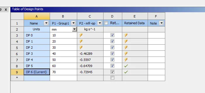
Showing mass flow rate as -0.72945 kg/sec
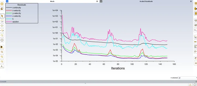
Showing residuals
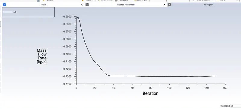
Mass flow rate plot
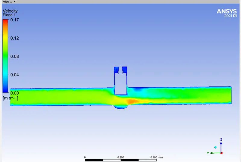
Velocity contour
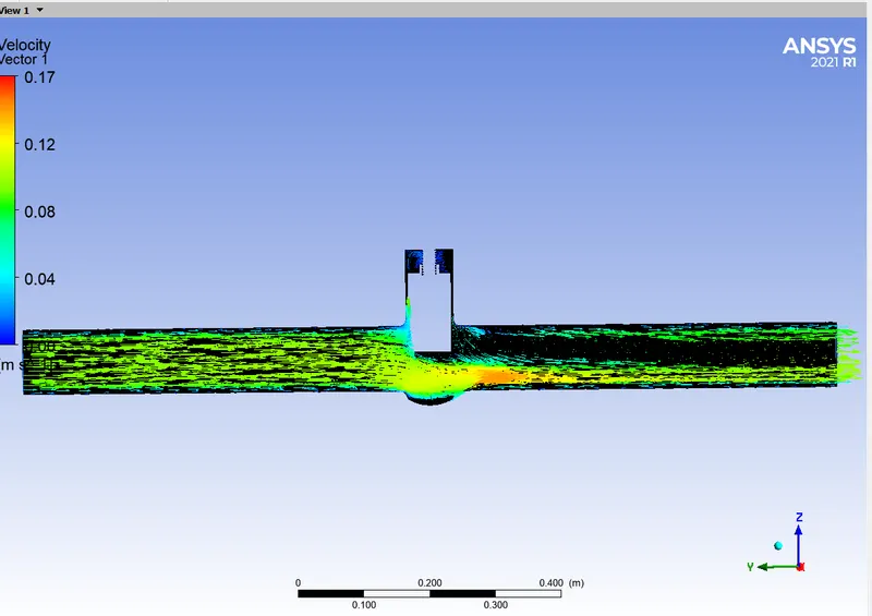
Velocity vector
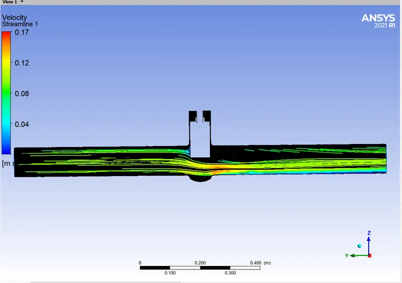
Streamlines
Note: Video uploade below
Case 8: 80 mm gate lift
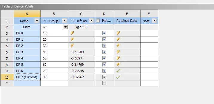
Showing masss flow rate as -0.82267kg/sec
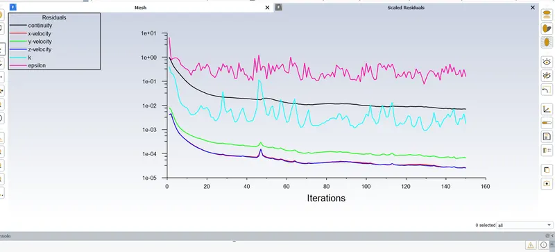
Residulas
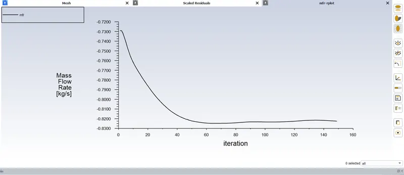
Mass flow rate plot
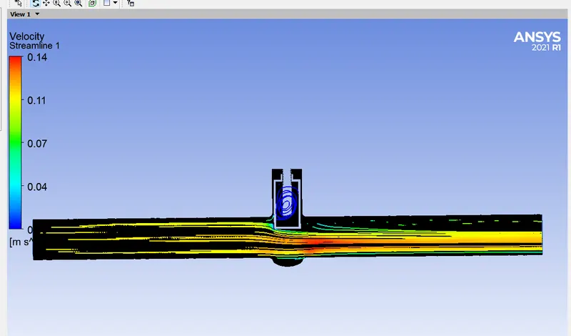
Streamlines
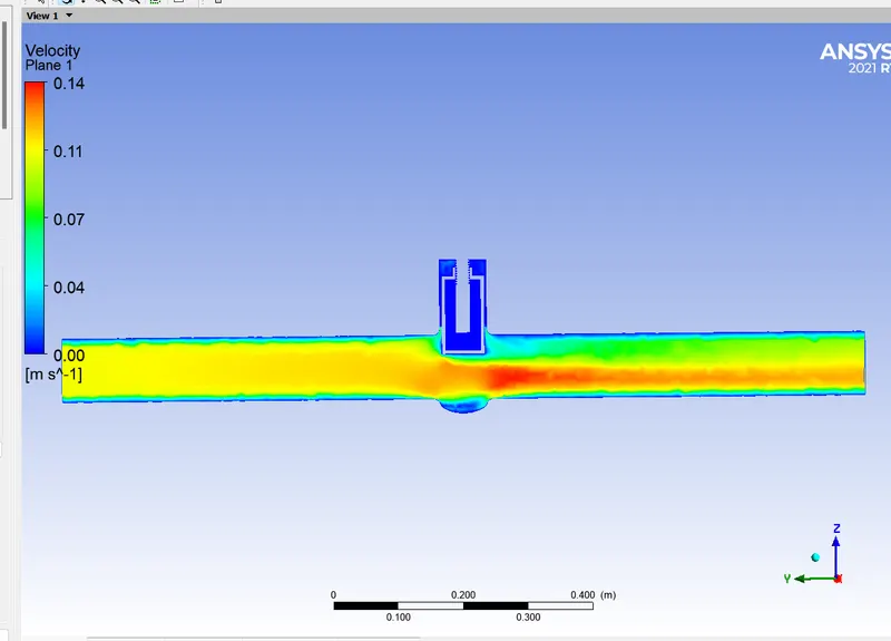
Velocity contour
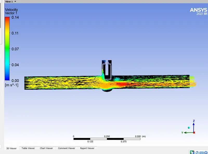
Velocity vector
Note: Video uploaded below
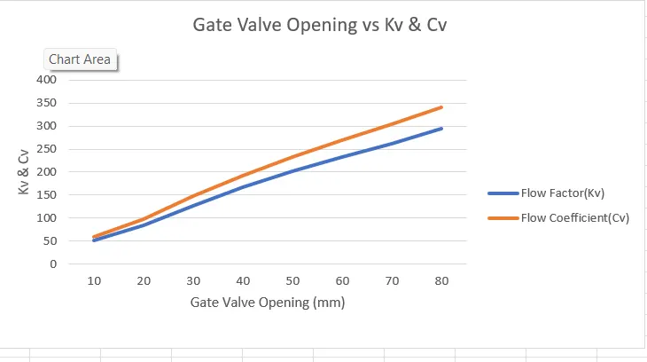
Calculate the flow coefficient and flow factor for each opening and plot the graph.
The flow coefficient of the valve is the efficiency of the gate valve to allow the fluid with respect to the opening.
Volume flow rate (Qactual)= mass flow rate / density of water
therefore, Q(actual) in m3/hr= Q(actual) in m3/sec X 3600
Flow Factor (Kv) = Q(actual)/ (Root of delta P/ S)
S-Specific gravityof water = 1
Flow coefficient (Cv) = 1.156 x Kv
Like this we can find Flow factor and flow coefficient for each gate valve opening.
Following table shows the flow coefficient & flow factor for each opening condition:
| Cases | Gate Valve Opening (mm) | Mass flow rate(kg/sec) | Flow Factor(Kv) | Flow Coefficient(Cv) | |
| 1 | 10 | -0.144 | 51.84 | 59.92 | |
| 2 | 20 | -0.233 | 83.88 | 96.96 | |
| 3 | 30 | -0.35392 | 127.404 | 147.279 | |
| 4 | 40 | -0.46289 | 166.640 | 192.636 | |
| 5 | 50 | -0.5597 | 201.492 | 232.924 | |
| 6 | 60 | -0.6470 | 232.92 | 269.255 | |
| 7 | 70 | -0.72944 | 262.598 | 303.563 | |
| 8 | 80 | -0.82067 | 295.44 | 341.530 | |
CONCLUSIONS:
* As per the gate valve opening increases, mass flow rate, flow factor and flow coefficients are also increasing.
* When the valve opening is small, velocity of flow increases at the bottom of the valve due to reduction in area.