Week 9 - Parametric study on Gate valve.
Aim: To simulate Gate valve .
Introduction & theory:
- A gate valve is generally used to completely shut off fluid flow or, in the fully open position, provide full flow in a pipeline. Thus it is used either in the fully closed or fully open positions. A gate valve consists of a valve body, seat and disc, a spindle, gland, and a wheel for operating the valve.
- The main advantage of a gate valve is the straight-through unobstructed passageway, which induces minimal pressure loss over the valve.
Working:
- Gate valves work by inserting a rectangular gate or wedge into the path of a flowing fluid. They are operated by a threaded stem which connects the actuator (generally a hand wheel or motor) to the stem of the gate. If the valve has a rising stem its position can be seen just by looking at the position of the stem.
- When fully open, a gate valve has no obstruction in the flow path and so has a very low pressure drop.
- One reason that gate valves are not normally used to regulate flow, is that the flow rate of the fluid is not proportional to the amount that the valve is open..
Flow coefficient& Flow factor:
Flow Coeff(Cv)
- The flow coefficient of a device is a relative measure of its efficiency at allowing fluid flow. It describes the relationship between the pressure drop across an orifice valve or other assembly and the corresponding flow rate.
- In more practical terms, the flow coefficient Cv is the volume (in US gallons) of water at 60 °F (16 °C) that will flow per minute through a valve with a pressure drop of 1 psi (6.9 kPa) across the valve.
Mathematically
Mathematically the flow coefficient Cv (or flow-capacity rating of valve) can be expressed as :

-
The metric equivalent flow factor (Kv) is calculated using metric units :

where,
- Kv is the flow factor
- Q is the flowrate
- SG is the specific gravity of the fluid
- ∆P is the differential pressure across the device
Modelling:
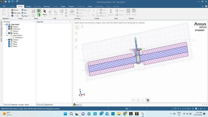
- Open_spaceclaim.
- Spaceclaim_file_open_Gatevalvefile.
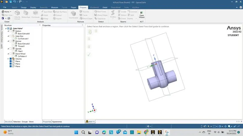
- spaceclaim__Prepare_volumeextract_ To Extract _fluidvolume
- spaceclaim_Pull_to extend the volumes .
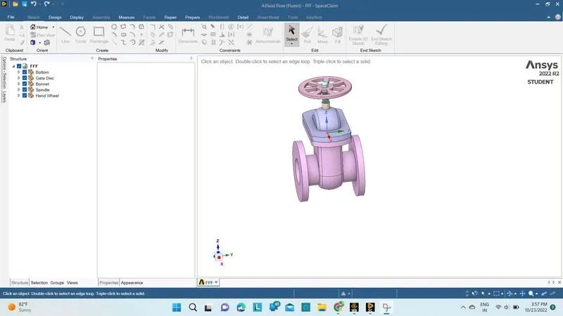
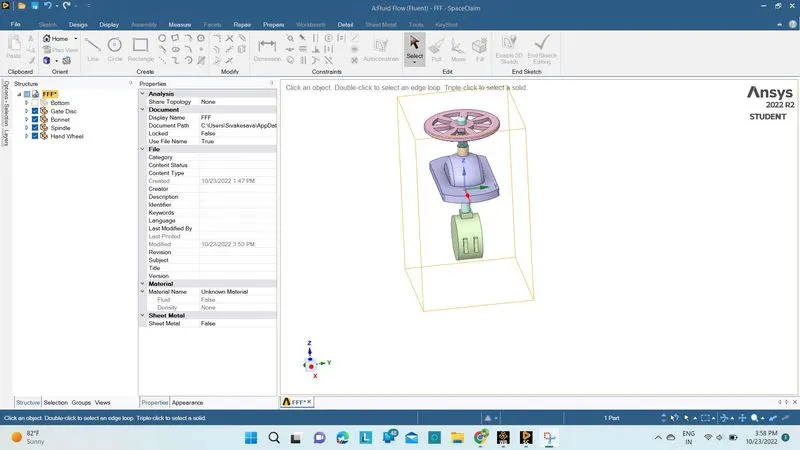
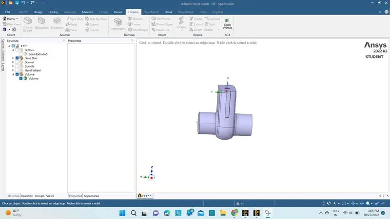
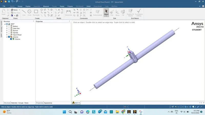
Mesh:
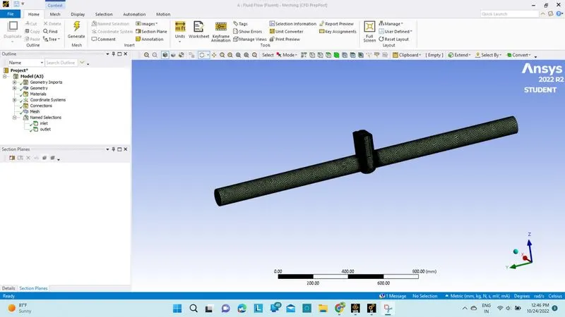
- Open_mesh
- Mesh_rightclick_generate mesh (10mm).
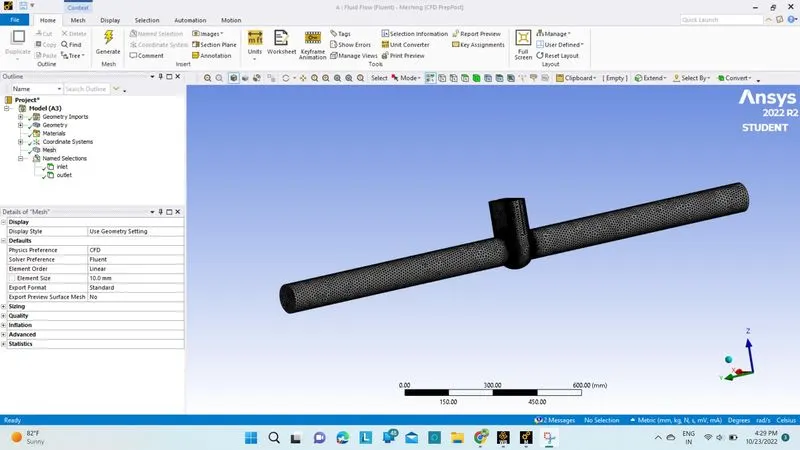
Fluent:
- Open_fluent
- Fluent_Enable Gravity
- Fluent_Enable steady.
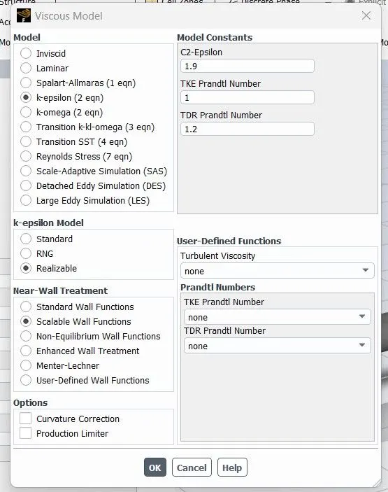
- Fluent_viscous_K-episilon_reliazable_scalable wall functions.
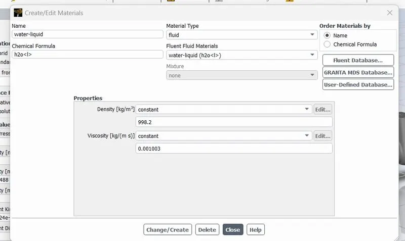
- Fluent_Materials_water(liquid)
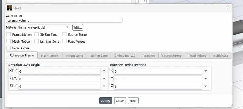
- Fluent_zones_set to water(liquid)
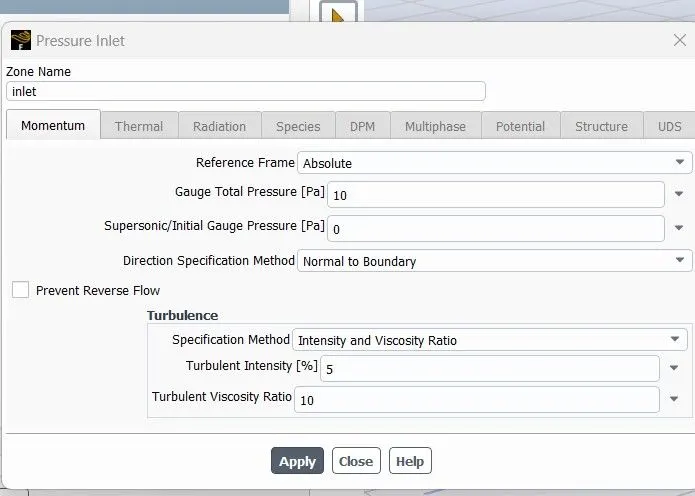
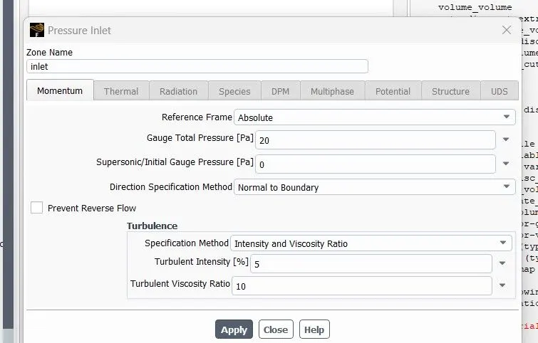
- Fluent_boundary conditions_give Pressure inlet.
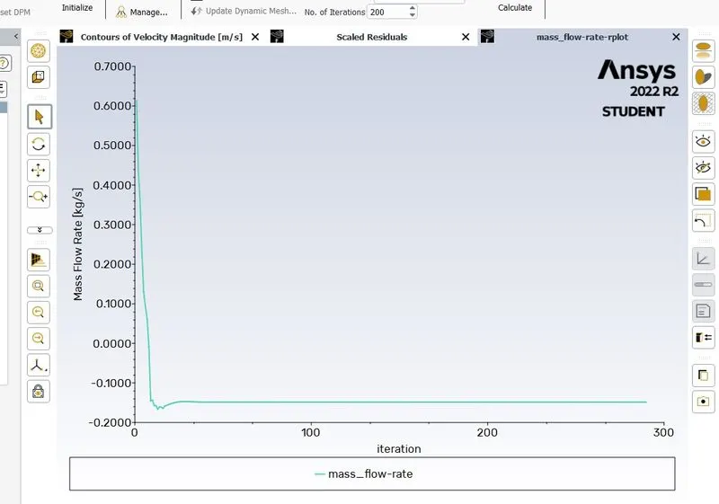
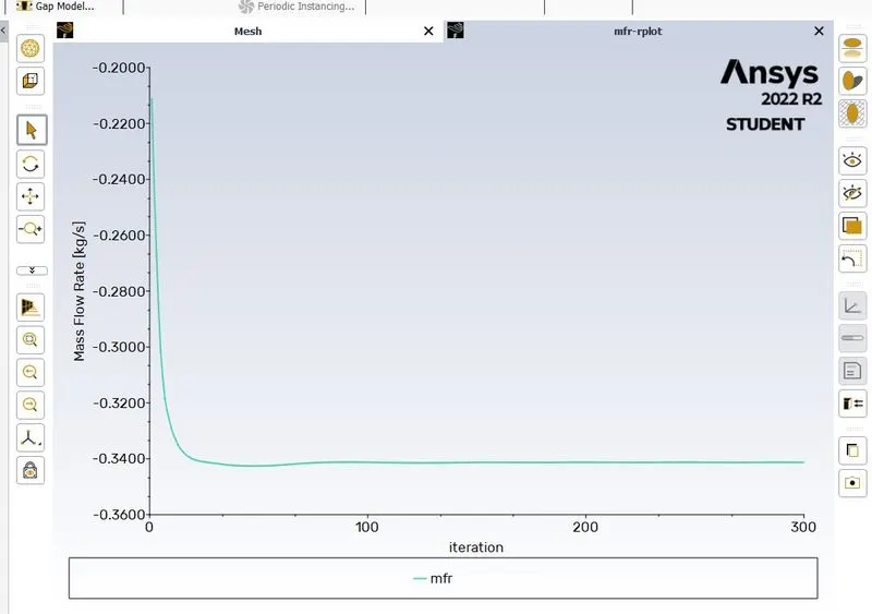
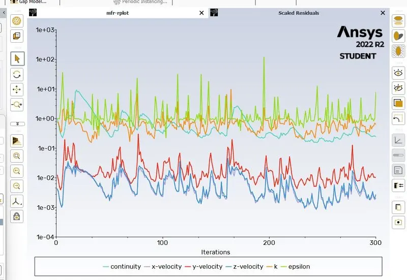
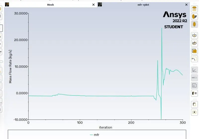
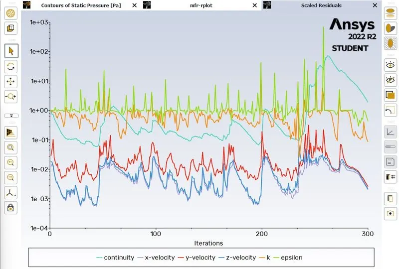
- Fluent_solutions_reportdefinitions_flux flow _mass flow rate.
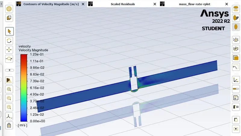
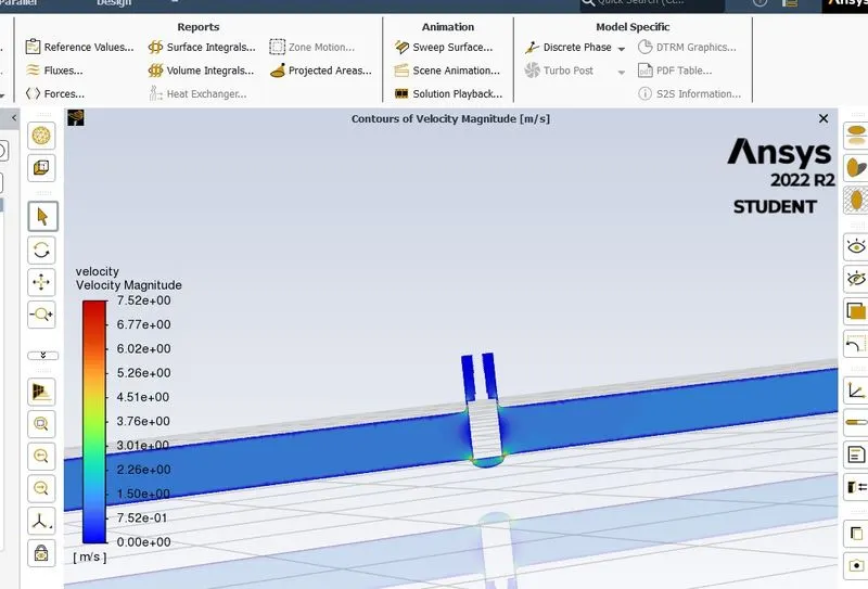
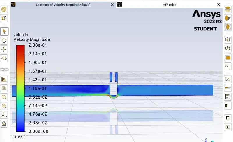
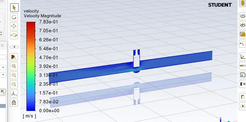
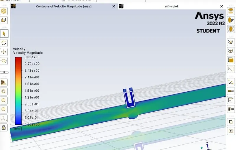
- fluent_resulrs_contours_create velocity contour.
Parametric Study:
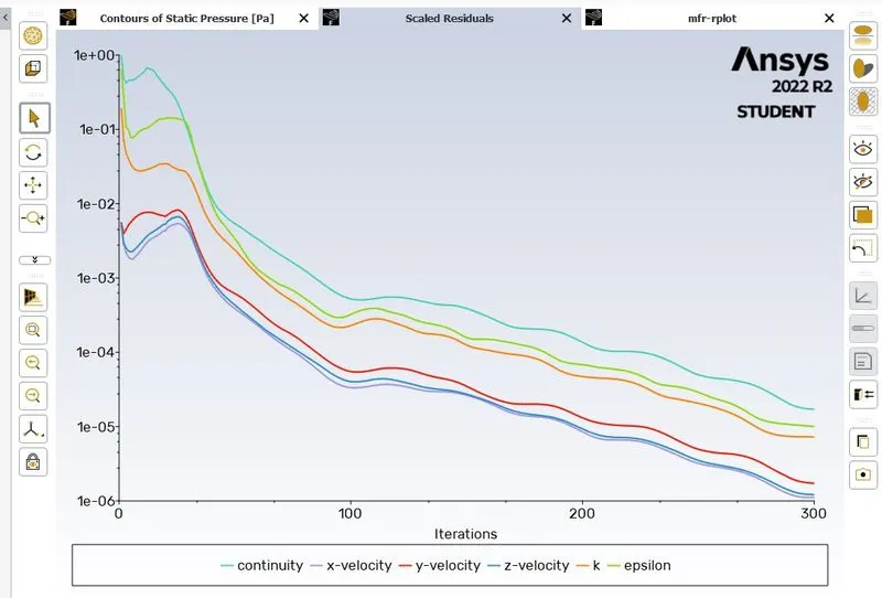
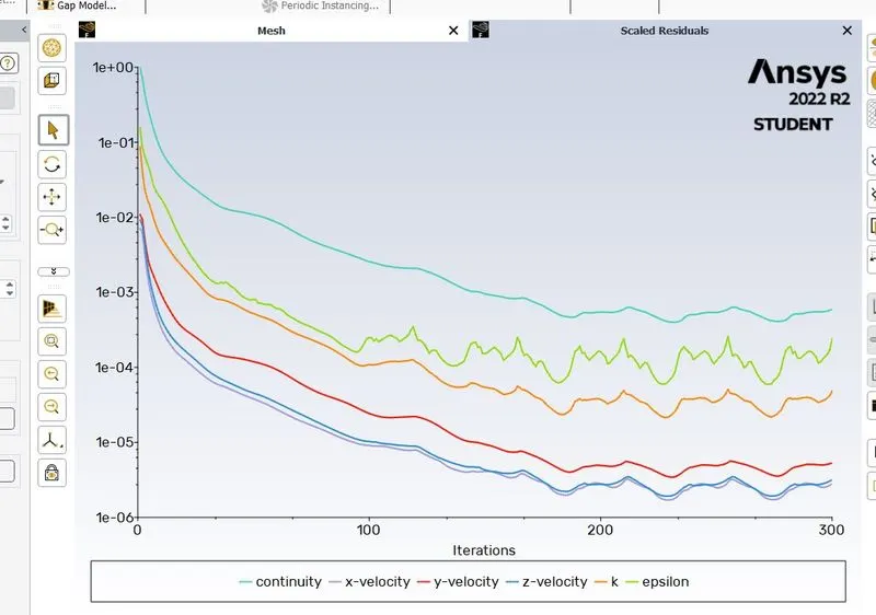
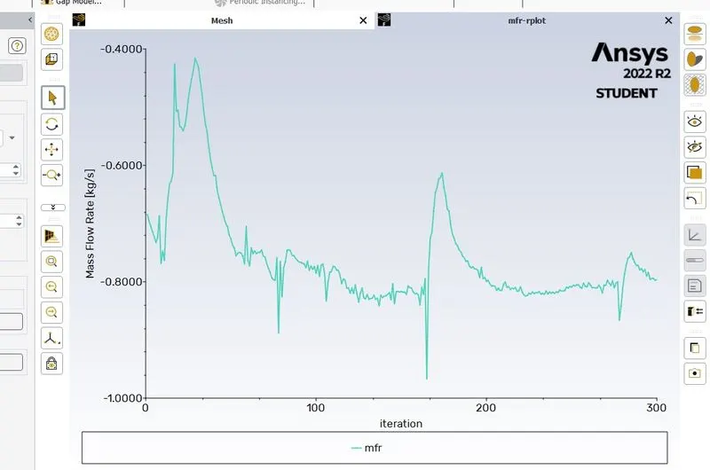
- To study the mass flow rate at the outlet of the Gate valve during different levels of Lift of gate disc.
- Open_spaceclaim
- spaceclaim_Move_select gate disc _(10mm)
- spaceclaim_groups_set parameter .
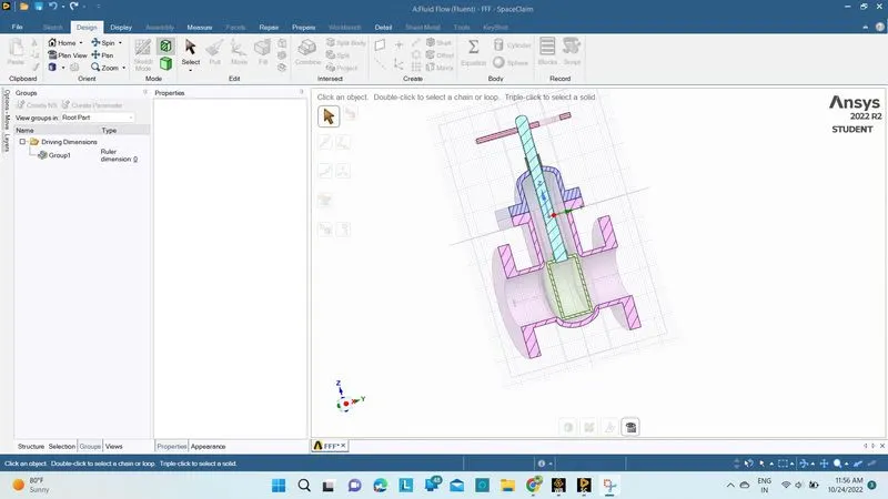
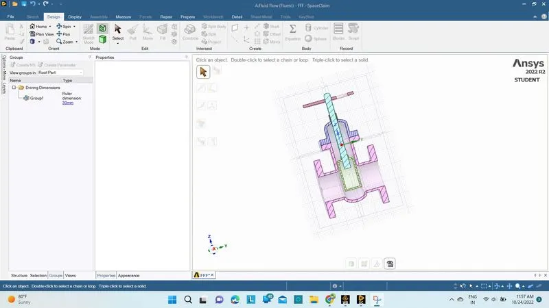
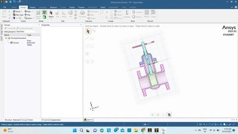
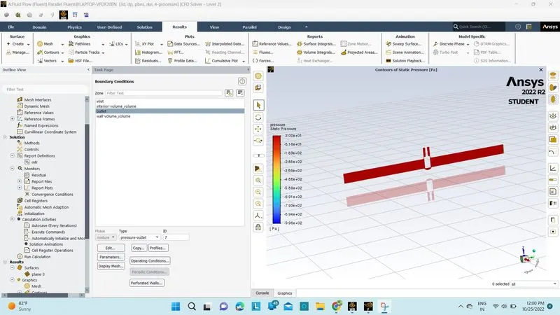
For 10mm;
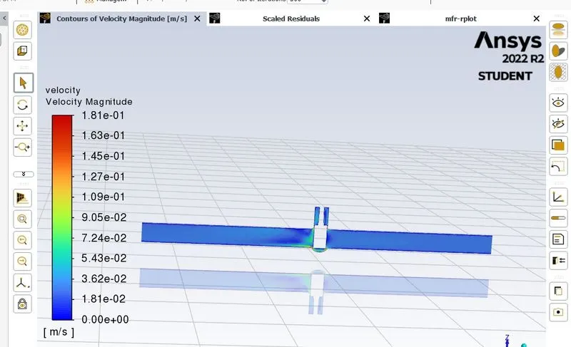
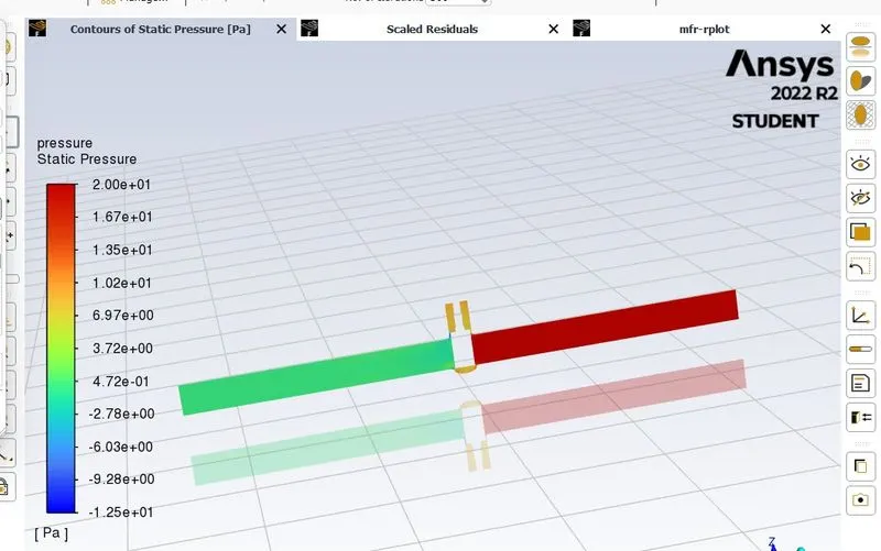
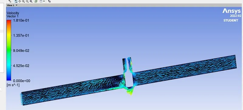
FOR 20mm;
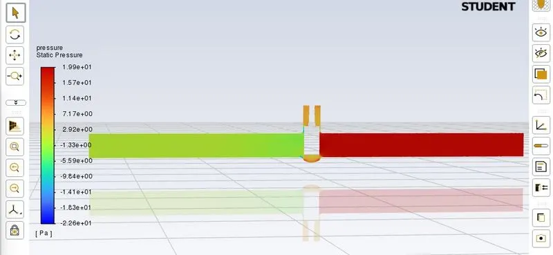
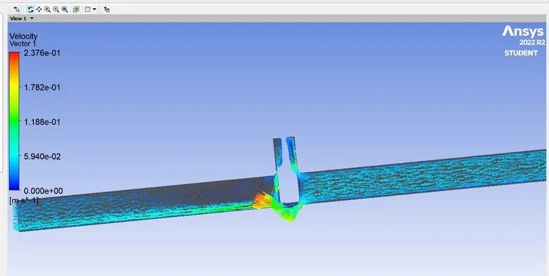
For 30mm;
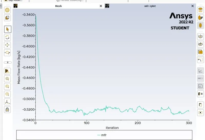
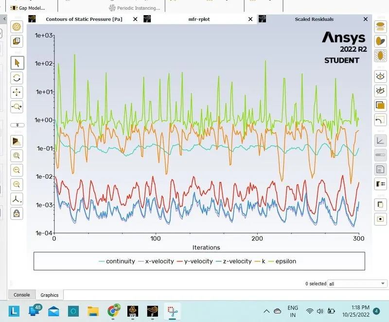
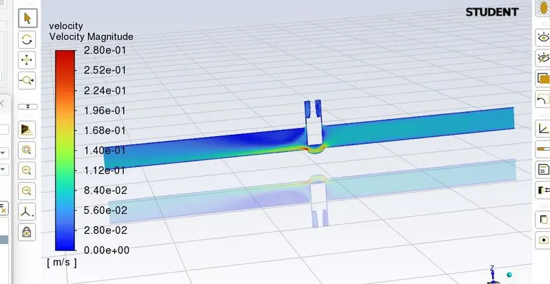
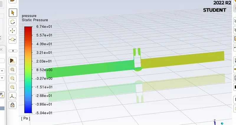
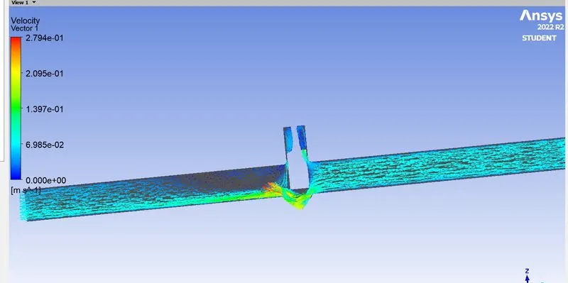
For 40mm;
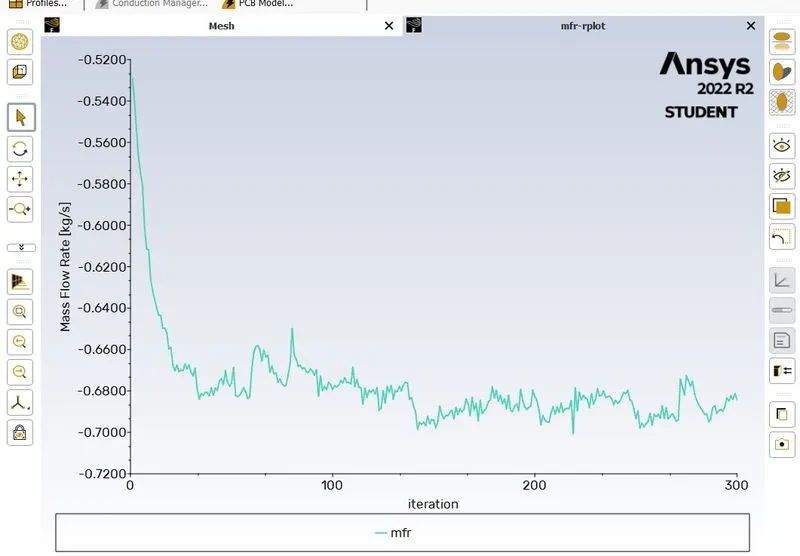
FOR 50mm;
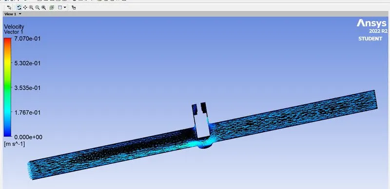
For60mm;
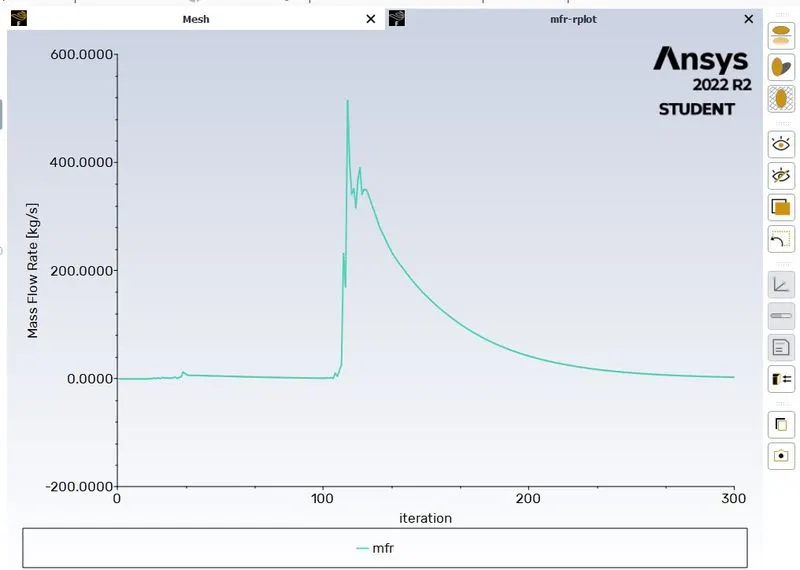
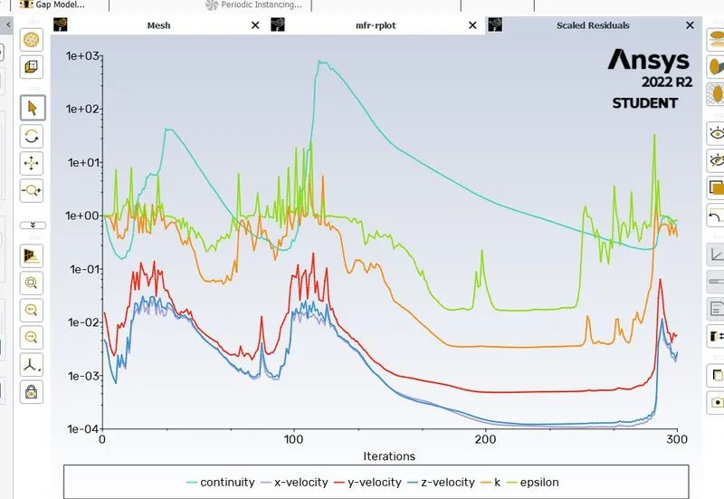
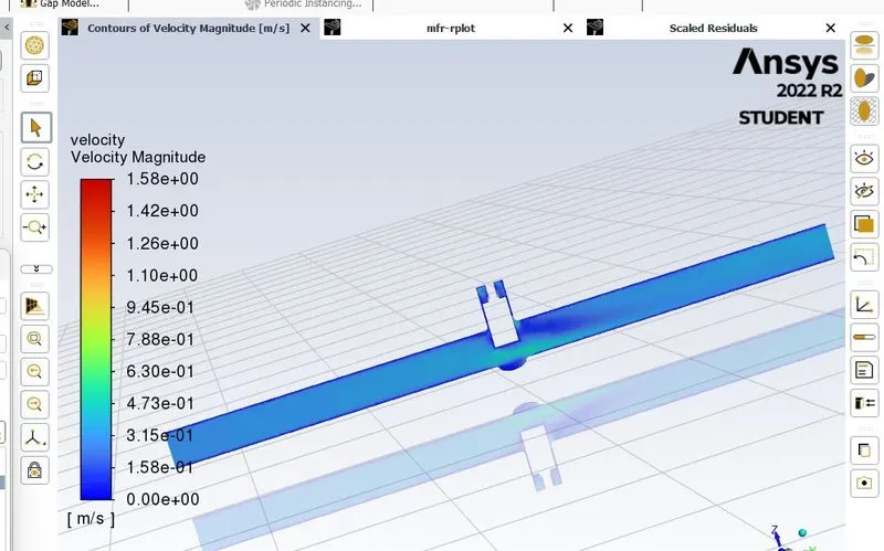
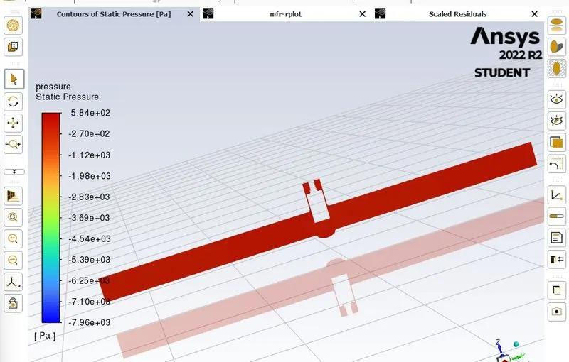
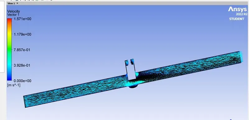
FOR 70mm;
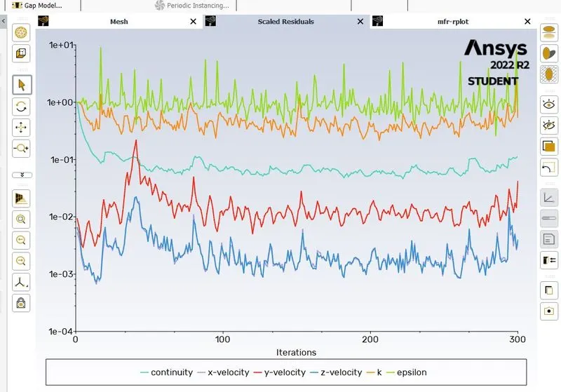
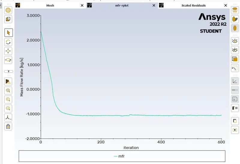
For 80mm;
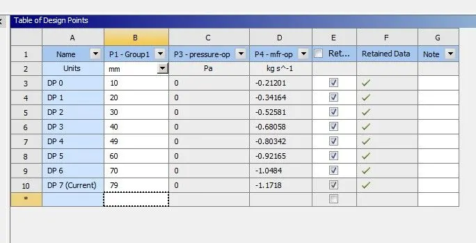
S.no	D	Q	         sg	dp	       Cv= C1*SQRT(D1/E1)
1	10	-0.21201	1000	20	        -1.499137087
2	20	-0.34164	1000	20	        -2.415759607
3	30	-0.52581	1000	20	        -3.718038166
4	40	-0.68058	1000	20	        -4.812427331
5	49	-0.80342	1000	20	        -5.681037301
6	60	-0.92165	1000	20	        -6.517049649
7	70	-1.0484	        1000	20	        -7.413307494
8	79	-1.1718	        1000	20	        -8.285877262
My observation:
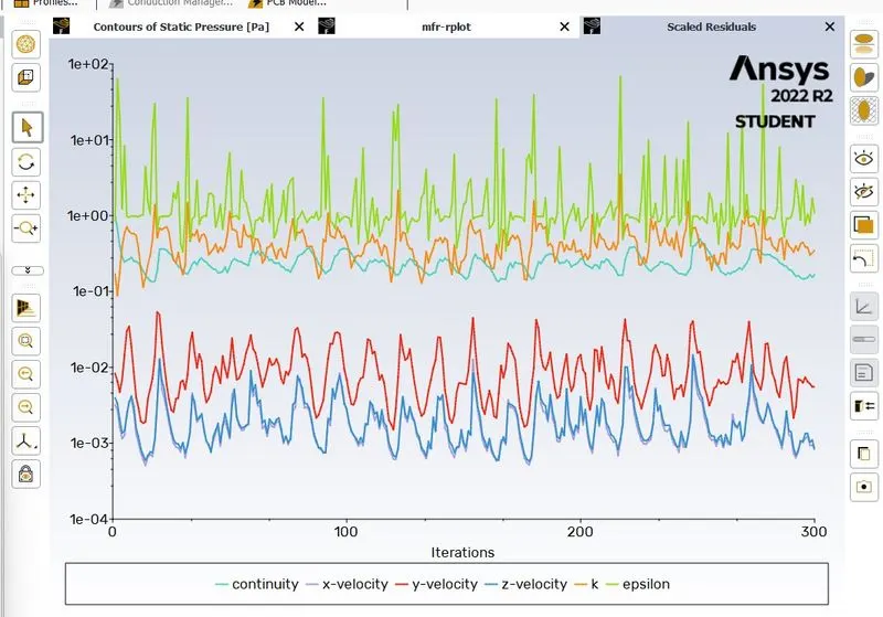
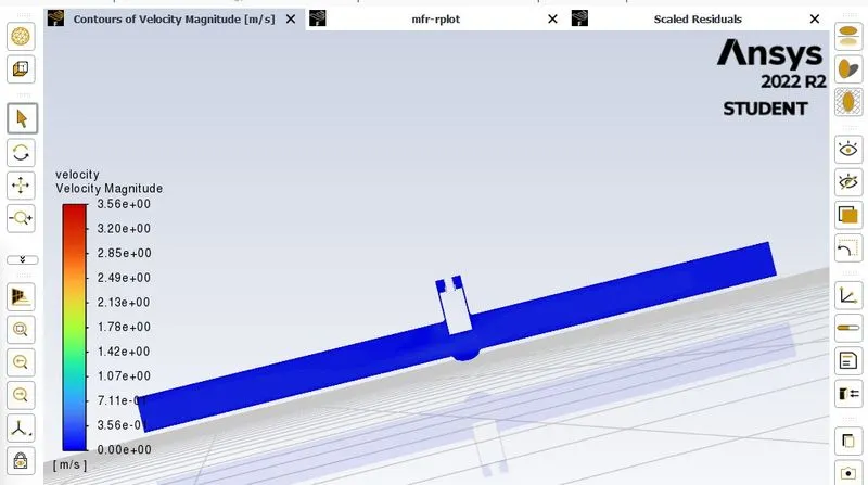
As per my observation,if displacement of gate valve increases the flow rate (a*velocity )increases ,& we observed in the mass flow rate values ie., for 10mm is -0.21201 &20mm is -0.34164 .when we obstruct the flow, velocity decreases at the obstructed region.
As per my knowledge area inceases=velocity increases
=pressure constant
area decreases= velocity constant
=pressure increases
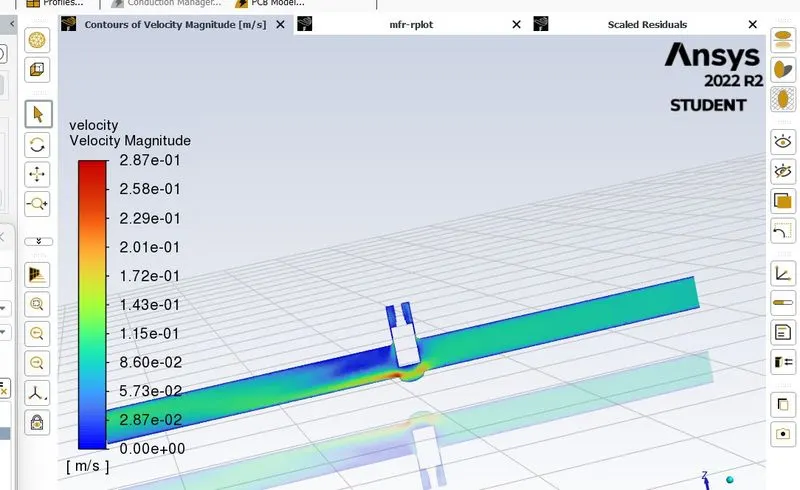
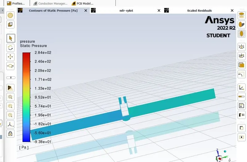
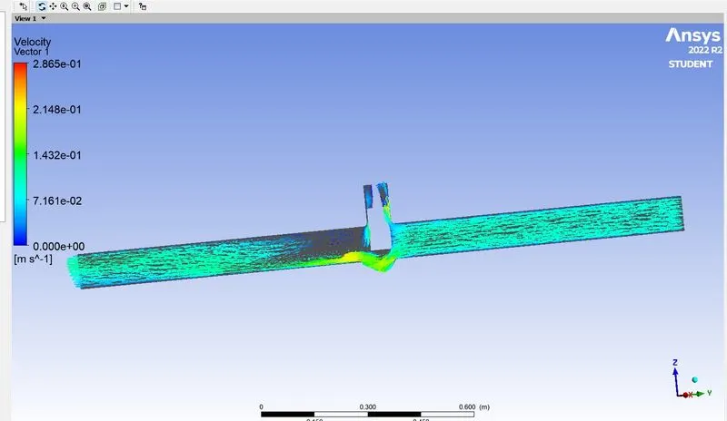
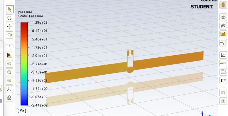
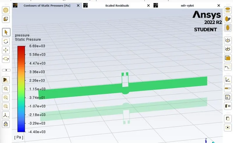
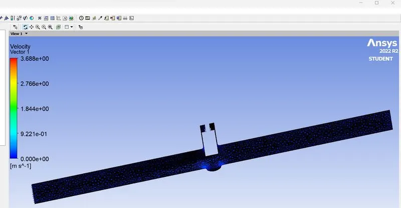
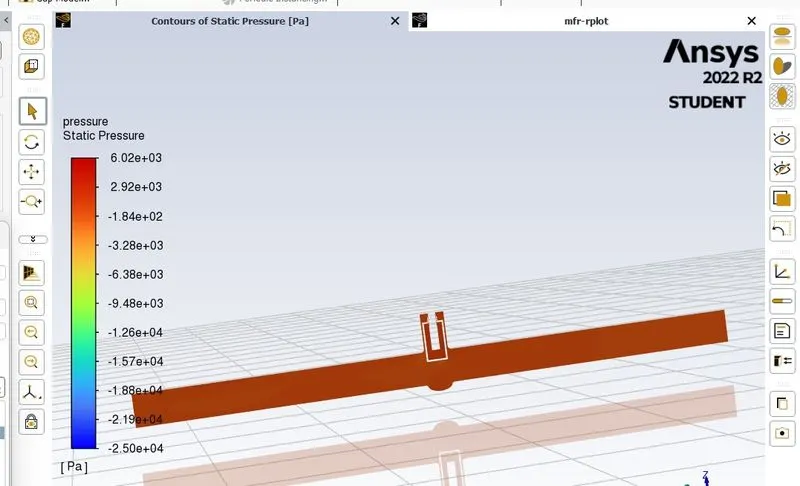
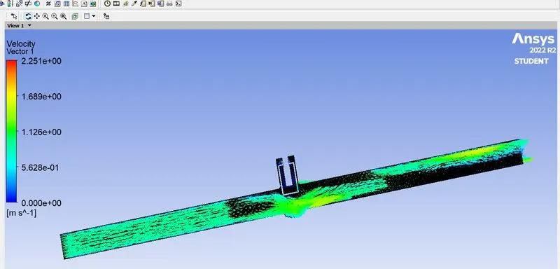
If we observe in the velocity & pressure profiles,we can clearly say we have more pressure drop due to the viscous forces applied by the gate valve,and its velocity constantly vary at that point
since we haven 20 pascals of pressure energy,for 10mm & 20mm
velocity=[0.181 0.145 0.0905 0.0181 0]
pressure =[20 16.7 6.97 -2.78 -0]
velocity=[0.238 0.214 0.119 0.0238 0]
pressure=[19.9 7.17 -1.33 -5.59 -0.226 0]
we can clearly say there is pressure drop with constant velocity and also we observe Stagnation point & wake region slightly.
- Gate valves are mainly used resistance to flow & to control the flow,etc.
- used in industrial, domestic, agricultural etc.,
My conclusion:
- There is a pressure drop.
- velocity constant.
- wake region..
- stagnation point.etc.,