Week 9 - Parametric study on Gate valve.
Aim:- Parametric study on Gate valve.
Objective:-
1) perform a parametric study on the gate valve simulation by setting the opening from 10 % to 80%.
2) Obtain the mass flow rates at the outlet for each design point.
3) Calculate the flow coefficient and flow factor for each opening and plot the graph.
4) Discuss the results of the mass flow rate and flow coefficient.
Tools used :-
1) space claim
Pull,Move,groups,create parameters,extract volume,supress for physics
2) Ansys mesh
Create mesh, create name selection
3) ansys fluent
gravity,turbulence model,boundary condition,material,report definition,Initialization,compute
4)CFD-Post
plane,velocity contour,velocity vector,streamline
Theory:-
Gate valve:-
Gate valve is a valve that opens by lifting the barrier or gate from the path of fluid flow. It is a linear moton valve and Its main function is to stop or allow the flow.
Gate valves are mostly used for fluids like heavy oil, light grease,non-flammable liquids , in pipeline , water, petroleum industries or those place where fluid flow takes place.
Gate valve is energy efficient valve because its movement direction is perpendicular to the flow direction as a result less power consumed for opening and closing the gate valves.
When it is opened at different positions it allows different amount of fluid flow and and gives different mass flow rate and its efficiency at allowing the flow is given by flow coefficient and flow factor , actually both are same only difference is
Flow Coefficient - Cv
Flow coefficient is based on the imperial units system and is defined as:
- The flow of water through a valve at 60 degree F in US gallon/minute at a pressure drop of 1 lb/in^2.
- The flow coefficient is commonly used in the U.S.
Flow Factor - Kv
The metric equivalent of the flow coefficient - Cv - is based on the SI-system and is called the Flow Factor - Kv
The flow factor - Kv - is defined as
- The flow of water with temperature ranging 5-30 degree C through a valve in cubic meters per hour (m^3/h) with a pressure drop of 1 bar.
- The flow factor is commonly used outside U.S.
Converting between Flow Coefficient Cv and Flow Factor Kv
The relationship between Cv and Kv can be expressed as:
- Cv = 1.156 Kv
- Kv = 0.862 Cv
The relationship between Flow coefficient or Flow factor and mass flow rate is given by
`Cv=Q sqrt((SG)/(DeltaP))`
`Kv=Q sqrt((SG)/(DeltaP))`
Where,
For flow coefficient
Q is the rate of flow (expressed in US gallons per minute),
SG is the specific gravity of the fluid (for water = 1),
ΔP is the pressure drop across the valve (expressed in psi).
For flow factor
Kv is the flow factor (expressed in m3·h−1).
Q is the flowrate (expressed in cubic metres per hour m3·h−1),
SG is the specific gravity of the fluid (for water = 1),
∆P is the pressure drop across the valve (expressed in bar).
Procedure :-
1) Preprocessing
Geometry
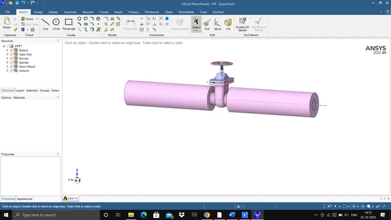
a) Import the gate valve geometry in space claim
b) Pull the side surface to extend the pipe length
c) Move the gate disc upward upto 10 mm and vary till 80mm with 10mm of interval as total dimension is 100mm so to open for 10% move 10mm and for 80% move 80mm.
d) Create parameters from groups option
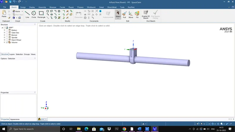
e) Now extract the fluid volume and update
f) Supress all other solid components using supress for physics.
Meshing :-
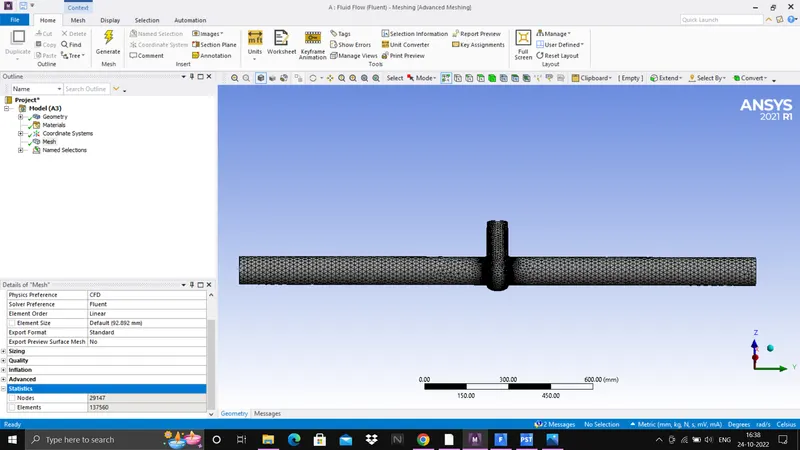
a) Open Ansys mesh for meshing of geometry
b) Generate mesh at base element size 92mm
c) Create name selection as inlet and outlet.
2) Solving
Solver
a) Open Ansys fluent solver
b) Enable gravity in z direction with -9.81m/s^2
c) Select pressure based solver and at steady state condition
d) In turbulence model, select k-epsilon realizable turbulence model
e) Now select material as water because here fluid flow through gate valve is water
f) Give boundary condition as
inlet - pressure-inlet - total gauge pressure -20 pa
outlet - pressure outlet - gauge pressure - 0 pa
g) Now create report definition of mass flow rate at outlet using surface report option in report definition
h) Now initial the problem and compute for 300 iterations
i) Here simulation has to be run at various openings from 10% to 80% , so 8 cases will be created & to do it at different opening without changing again and again in space claim use create parameters which is created above in geometry. For it go to project page click parameters which is created there now create 8 design points and give gate valve lift value which is
| Cases | gate disc lift value |
| DP1 | 10 |
| DP2 | 20 |
| DP3 | 30 |
| DP4 | 40 |
| DP5 | 50 |
| DP6 | 60 |
| DP7 | 70 |
| DP8 | 80 |
j) Then just update diffrent DP( DESIGN POINTS) and mass flow rate at different position will be found out also note down pressure at outlet to calculate pressure drop.
3) Postprocessing
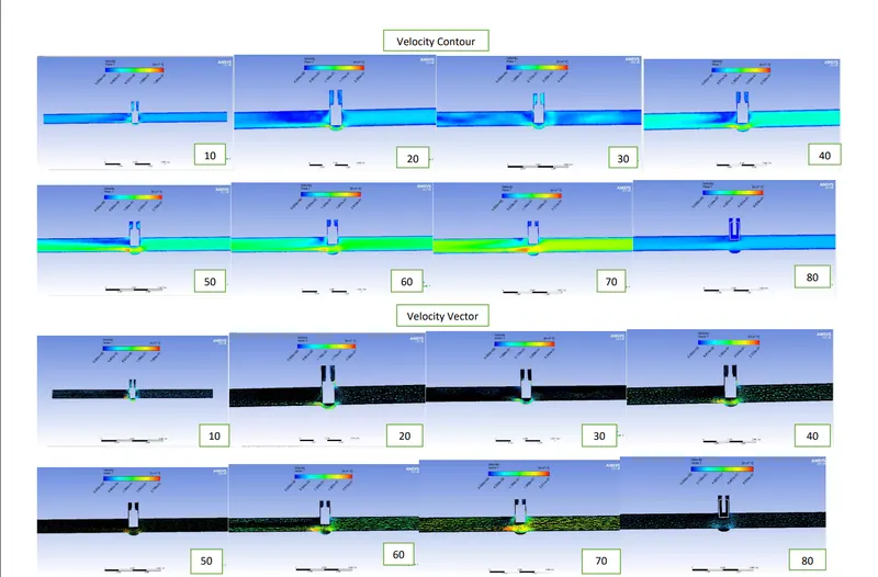
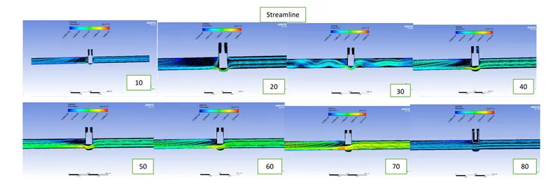
a) Create velocity contour ,velocity vector and streamline at different gate valve positions
b) Calculate Flow coefficient and flow factor using mass flow rate obtained above , here water is fluid material so its specific gravity is 1.
Result:-
| Cases -Lift (mm) | Q(Kg/s) | Q(gallon/min) | Inlet pressure(pa) | outlet pressure(pa) | pressure difference(pa) | pressure difference(psi) | Cv | Kv |
| 10 | 02088 | 3.310 | 20 | 0.3778 | 19.6222 | 0.002845 | 62.0564 | 53.4926 |
| 20 | 0.3373 | 5.346 | 20 | 0.9677 | 19.0323 | 0.002760 | 101.7593 | 87.7165 |
| 30 | 0.3619 | 5.736 | 20 | 3.9028 | 16.972 | 0.002334 | 118.7295 | 102.3448 |
| 40 | 0.6521 | 10.336 | 20 | 3.6240 | 16.376 | 0.002375 | 212.0902 | 182.8217 |
| 50 | 0.7681 | 12.175 | 20 | 5.2047 | 14.7953 | 0.002145 | 262.8786 | 226.6013 |
| 60 | 0.8935 | 14.162 | 20 | 6.8449 | 13.1551 | 0.001907 | 324.3017 | 279.5480 |
| 70 | 1.003 | 15.898 | 20 | 8.5448 | 11.4552 | 0.001661 | 390.0835 | 336.2519 |
| 80 | 1.1167 | 17.700 | 20 | 10.6411 | 9.3589 | 0.001357 | 480.4888 | 414.1813 |
Contours:-
Velocity contour and velocity vector at each gate valve lift
Streamilne at each gate valve lift
Conclusion:-
Parametric Simulation on Gate valve at various gate position ranging from 10% to 80% opening has been done on Ansys fluent and mass flow rate obtained also flow coefficient and flow factor is calculated for each gate lift.
As opening should vary from 10% to 80% so there will be 8 cases or 8 simulation for each gate lift and to change gate lift it is not necessary to move gate valve for each lift by opening again and again in space claim ,so it has been done using parameters by just updating all design points and just through this we got all the result .
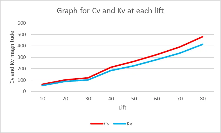
Also, Flow coefficient and flow factor is calculated using above formula and is tabulated above and graph is plotted for each lift.
From result it is observed that as opening is increasing mass flow rate is increasing and output pressure is also increasing,as inlet pressure kept constant for each cases and at very small opening there will be more ostruction to flow and due to it there will be less output pressure which can be seen in result table also, at 10% opening there is very less output pressure. Also,both flow coefficient and flow factor is increasing by increasing opening which can be seen in graph.