Week 9 - Parametric study on Gate valve.
AIM:
For this challenge, you will have to perform a parametric study on the gate valve simulation by setting the opening from 10 % to 80%.
- Obtain the mass flow rates at the outlet for each design point.
- Calculate the flow coefficient and flow factor for each opening and plot the graph.
- Discuss the results of the mass flow rate and flow coefficient. `
INTRODUCTION:
GATE VALVE:
A gate valve, also known as a sluice valve, is a VALVE that opens by lifting a barrier (gate) out of the path of the FLUID. Gate valves require very little space along the pipe axis and hardly restrict the flow of fluid when the gate is fully opened. The gate faces can be parallel but are most commonly wedge-shaped (in order to be able to apply pressure on the sealing surface).
VALVE CONSTRUCTION:
Common gate valves are actuated by a threaded stem that connects the actuator (e.g. handwheel or motor) to the gate. They are characterised as having either a rising or a nonrising stem, depending on which end of the stem is threaded. Rising stems are fixed to the gate and rise and lower together as the valve is operated, providing a visual indication of valve position. The actuator is attached to a nut that is rotated around the threaded stem to move it. Nonrising stem valves are fixed to, and rotate with, the actuator, and are threaded into the gate. They may have a pointer threaded onto the stem to indicate valve position, since the gate's motion is concealed inside the valve. Nonrising stems are used where vertical space is limited.
METHODOLOGY:
ACTIVE PARAMETERS:
An Active parameter dynamically generates a list of value options for a build parameter using a Groovy script or a script from the Scriptler catalog.
ADAPT FLUID VOLUME TO CHANGING SOLID BOUNDARY.
ANALYSIS:
the analysis is carried out in this challenge is PARAMETRIC ANALYSIS OR PARAMETRIC STUDY.
A parametric analysis, also known as a sensitivity analysis, is the study of the influence of different geometric or physical parameters or both on the solution of the problem.
The parametric study is possible for concept design because the number of design variables to perturb is usually small. A spreadsheet with a proper formula defined among cells is well suited to support the parametric study.
PROCEDURE:
The GATE VALVE SIMULATION will be analysis in the ansys workbench with the help of the fluid flow (fluent).
The fluid flow simulations contains several steps are :
1.geometry
2.Meshing
3.Setup
4.Solution
5.Results.
By the help of all this software the rayleigh taylor instability is analysied properly and completely.
GEOMETRY:
The ansys fluent is opened in that the double click on geaometry ,the spaceclaim is opened.
Ansys - fluent - geometry - space claim. In the space claim Drag - drop model.
.
in the Prepare - Volume extract - edges - inlet and outlet & top of the bottom.
the volume is generated in the flow field.
Design - pull - select inlet - drag - put value as 800mm. the model length is increased ,it is helps to simulate the gate valve.
Gate disc visible -Design - Move - Component - Drag in Z direction - set as 10mm - Parametrized (P) symbol - Click Group 1 is created.
Suppress the solid geometry bottom, disc - bonnet, spindle, handwheel. Only fluid volume exist - close.
Fluid - Volume - Section mode in design - Click in YZ plane. To set cut through section of plane.
Fluid not adapt to the left gate disk.
Click side arrow volume(expand) - Right click the volume - Update volume body in context.
Spindle Visible - then do volume body in context so you get correct fluid volume.
Bottom visible - pull - Outer round phase 800mm on both side.
Volume - Update in context - Orange outline - volume body.
MESHING:
The model is update din the ansys workbench and then the double click of the meshing results the opening of the meshing.
after model is loaded in the meshing interface,
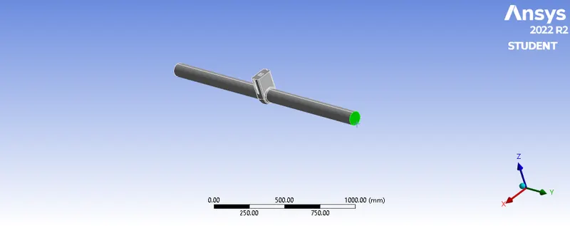
Name selection is carried out:
inlet :
outlet :
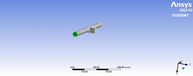
Generation of mesh is carried out in the element size of 20mm.
the meshed gate valve is:
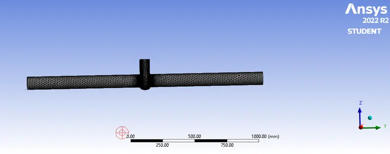
this is the meshing part of this gate valve simulation.
finally the mesh is also updated in the ansys workbench.
SETUP:
The ansys fluent is opened with the Double Precision with 4 solving processor.
the fluent is opened then model is loaded in the interface becomes,
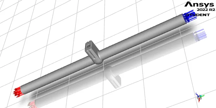
In this simulation the steady state is used , pressure based solver is used.
Enable gravity Z = -9.81 m/s in the z-direction.
Materials - Fluent database - water liquid
Cell Zone - water liquid - ok.
In the setup physics deck in the
Boundary condition - inlet - pressure inlet - gauge total pressure (10) & ok.
Outlet - default.(use the zore gauge pressure is output.)
Viscous model - K-epsilon - Reliazable - scalable wall - ok.
Definition - New - flux report - mass flow rate - outlet - ok. by this the mass flow rate report is generated.
Result - create - plane - create.
Contours - new - velocity - plane - save/display.
Solving - active - create - solution animation - click contour - change view - ok.
250 iteration - calculate.
Report - definitions - manage - compute - answer came and console.
Report - definition - create output parameter box click ok and apply.
Initalize from inlet and hit calculate.
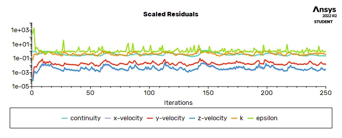
the residual of the gate valve in the parematric study is :
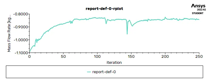
the mass flow rate in the gate valve is shown:
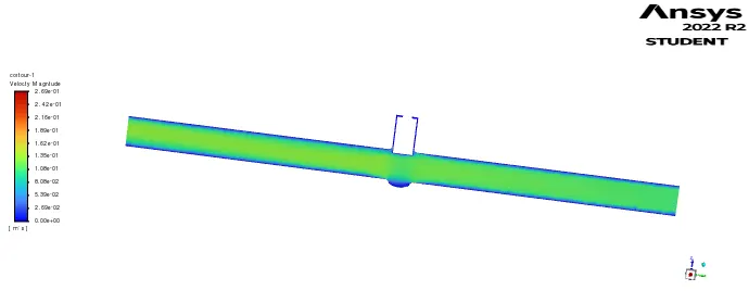
 the contour velocity of the gate valve in this proportion is shown:
and the model is updated in the ansys workbench.
PARAMETRIC STUDY:
The parametric study is possible for concept design because the number of design variables to perturb is usually small. A spreadsheet with a proper formula defined among cells is well suited to support the parametric study.
IN this gate valve model is after selecting parametric valve is the new deck is opened in the ansys workbench.
the parametric study is opened then the input is given in to 10% to 80% .
then finally all the analysis is succesfully carried out.
RESULTS AND CONCLUSION:
FLOW COEFFICIENT:
The flow coefficient of a device is a relative measure of its efficiency at allowing FLUID flow. It describes the relationship between the PRESSURE DROP across an ORIFICE valve or other assembly and the corresponding FLOW RATE.
Mathematically the flow coefficient Cv (or flow-capacity rating of valve) can be expressed as :

where:
- Q is the rate of flow (expressed in US gallons per minute),
- SG is the SPECIFIC GRAVITY of the fluid (for water = 1),
- ΔP is the pressure drop across the valve (expressed in psi).
FLOW FACTOR:
The metric equivalent flow factor (Kv) is calculated using metric units :

where:
- Kv is the flow factor (expressed in m3·h−1).
- Q is the flowrate (expressed in cubic metres per hour m3·h−1),
- SG is the SPECIFIC GRAVITY of the fluid (for water = 1),
- ∆P is the differential pressure across the device (expressed in bar).
Kv can be calculated from Cv using the equation:
