Week 9 - Parametric study on Gate valve.
AIM- To perform parametric study on Gate valve by simulating for gate opening at 10% & 80% . Calculate flow coefficient and flow factor ,Also plot mass flow rate with contours.
GATE VALVE
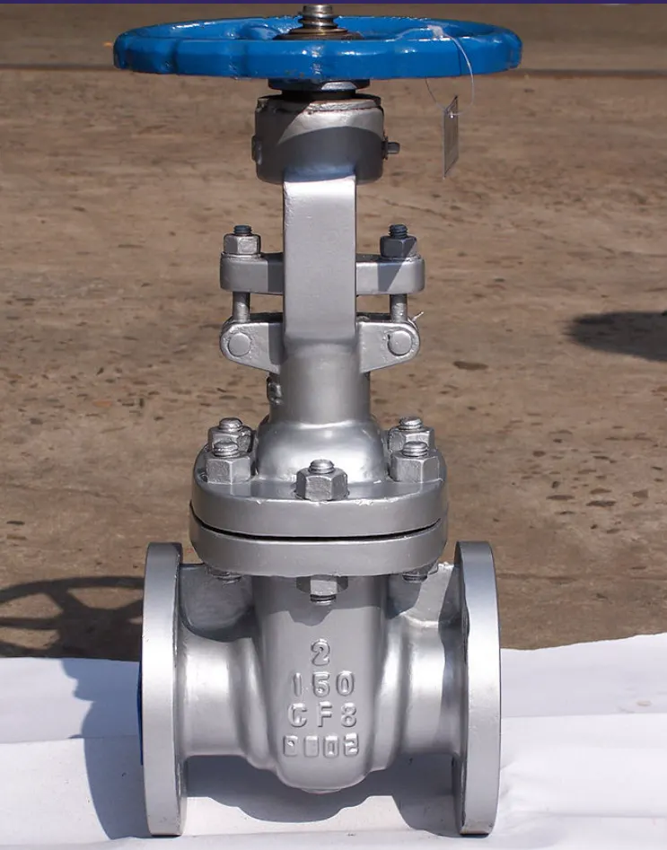
A gate valve, also known as a sluice valve,is a valve that opens by lifting a barrier(gate) out of the path of the fluid. Gate valves require very little spacing along the pipe axis and hardly restrict the flow of fluid when gate is fully opened. The gate faces can be parallel but are most commonly wedge-shaped,Which is to apply pressure on sealing surface.
THEORY
Gate valves work by inserting a rectangular gate or wedge into the path of flowing fluid(water).They are operated by thread stem which connects the actuator(hand wheel or motor) to the stem of gate. If the valve has a rising stem its position can be seen by just looking at stem. Agate valve is used to control the fluid flow through lifting and descending the gate. A gate distinct feature is to provide an unobstructed path.
When the gate isfully opened there is nor restriction to flow hence the pressure drop is low comperitively.Generaly the gate valve are fully closed or open may experince vibration which may lead to excessive wear. Its main components are seat,body,gate,stem,bonnet and actuator. The primary mechanism is straight forward where handwheel is rotated to move gate up via threads.they require more than 360-degree turn to fully open the valve.
Gate valves are widely used for all type of applications and are suited for for both above or underground installation.they are suitable for fluids including steam, water,oil & gas etc.
Parametric study
one of the best ways to get value of your simulationis to do parametric analysis.With very little marginal work a completed model can be parameterized to simulate scenerios limited only by your computational time and resources.As you move forward in your design,you can visualise the impact that changing certain parameters can have on design. The parameters can include dimensional parameters.
A parametric study requires designs, parameters,configuration generated etc. After this we can create scenerios for computing result and accesing that result with analytical.
Flow coefficient
The flow coefficient of device is a relative measure of its efficiency at allowing fluid flow. It describes realtion between pressure drop across orifice valve or other assembly and corresponding flow rate. Mathameticaly the flow coefficient (Cv)can be expressed as
`Cv= Q * sqrt((SG)/(triangleP)`
where
Q= rate of flow
SG= specific gravity(1 for water)
`triangleP`= pressure drop
Flow factor
The metric quivalent flow factor(Kv) is calculated using metric units
`Kv= 0.865*Cv`
STEPS FO SOLVING
- First we open geometry in spaceclaim and use PULL tool to extrude surfaces of 500mm at both side of valve for proper simulation result.
- Then we use MOVE tool to operate gate lifting conditions by creating parameters at 10%(10mm) to 80%(80mm) as the length between pipes is 100mm ,So the 1%=1mm.
- After creating parameter we extract volume by selecting edges for inner volume.
- We the check move command impact by changing values in parametres and checking in split body view if gate opening process is simulated.
- Then we suppress al parts for physics other than volume.
- We create mesh for 10 mm and open in give name selectin inlet & outlet.
- The we open in solver ANSYS FLUENT. Giver general settings presure based model, staedy state and gravity at z axis -9.81 with k-epsillon model with RNG.
- Then we add water as material nad change volume to water and give inlet boundary condition with pressure inlet and 20 Pa as pressure input.
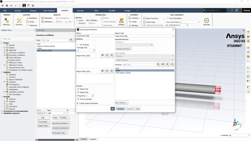
- Then we plot for mass flow rate as report and initialize and run for 350 iterations.
Solving with Snippets
Geomety
We open geometry file spaceclaim and use pull command to craete surface extrude for 500mm each side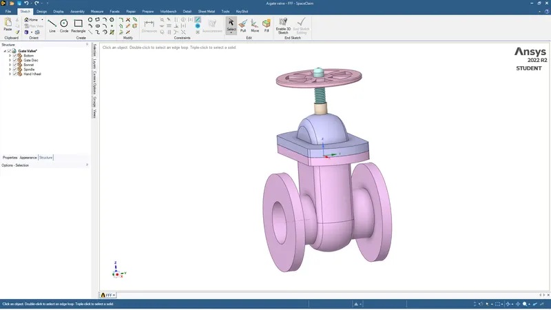
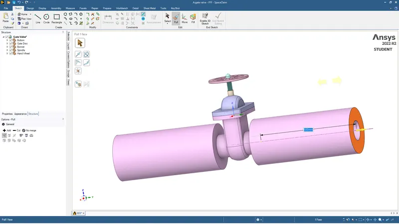
After creating surface extrude we Use MOVE tool for moving gate as body to 10 mm and the we got to groups and create parameter as shown below.
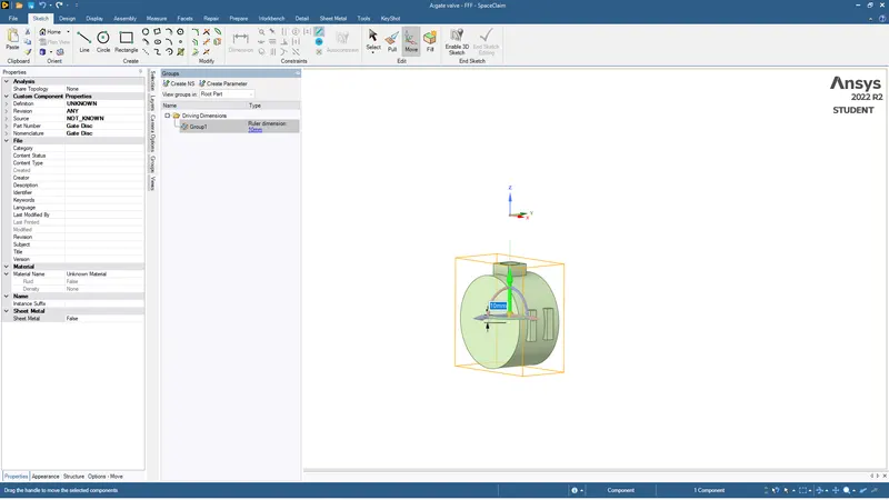
Then we extract volume by going to prepare and selcting edges for extracting volume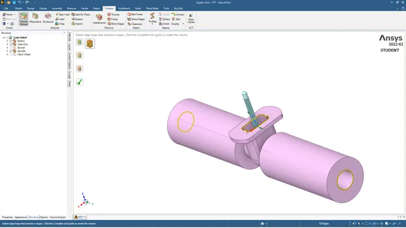
After volume is extracted we changes the gate position in parameter and see if the movement of gate is appropriate by using cut section view
View at gate =0mm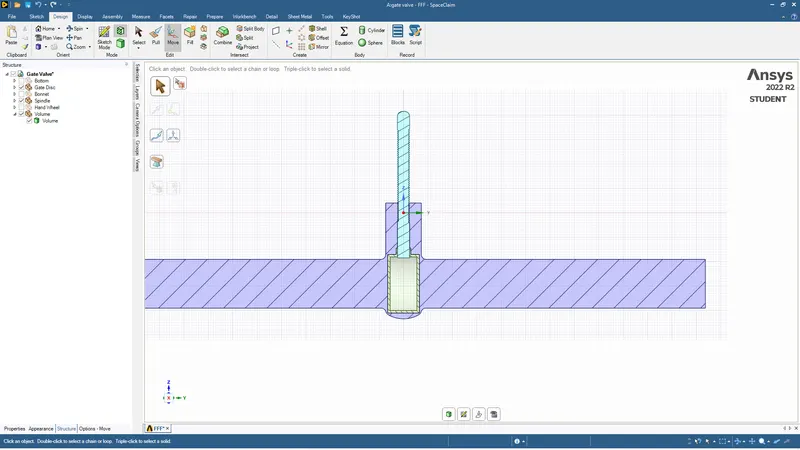
Then we click and change parameter to 10 and right click at volume to update the volume and we see result as below
View at 10mm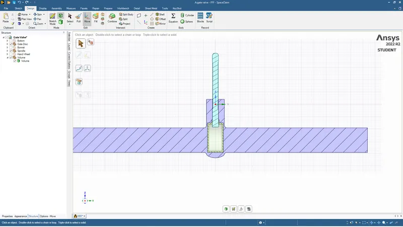
AFter we verify movement we supress al parts for physics other than volume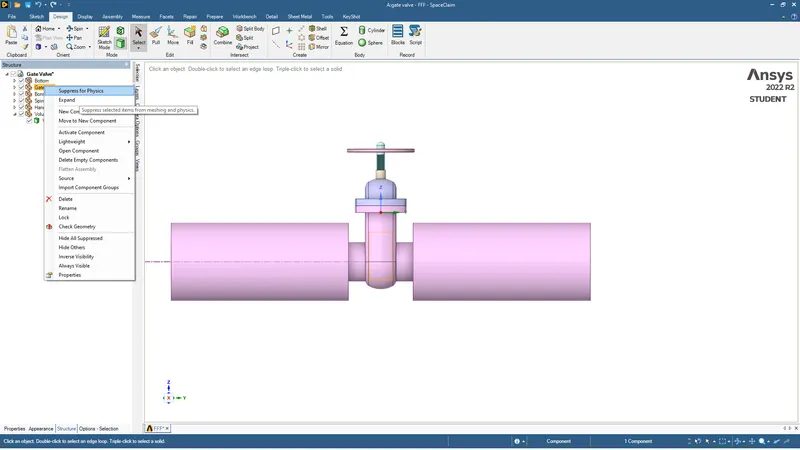
Meshing
We open the geometry in mesh and rather than default we generate mesh for 10mm so we dont have to create the sizing for curvature the general mesh will be sufficient for good results.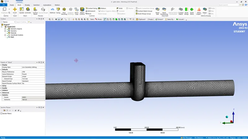
After meshing we give name selection for boundary conditions
INLET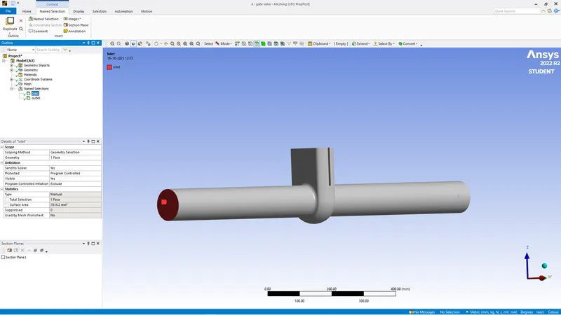
OUTLET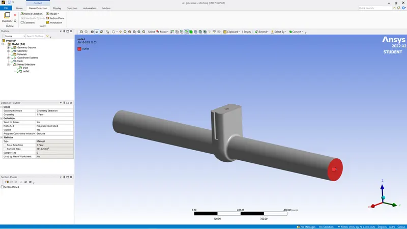
After this we open the meshed body in solve ANSYS FLUENT.
SOLVE
FIrst we give general settings for pressure-based, Steady state, Gravity at z axis -9.81, K-epsillon solver(RNG).
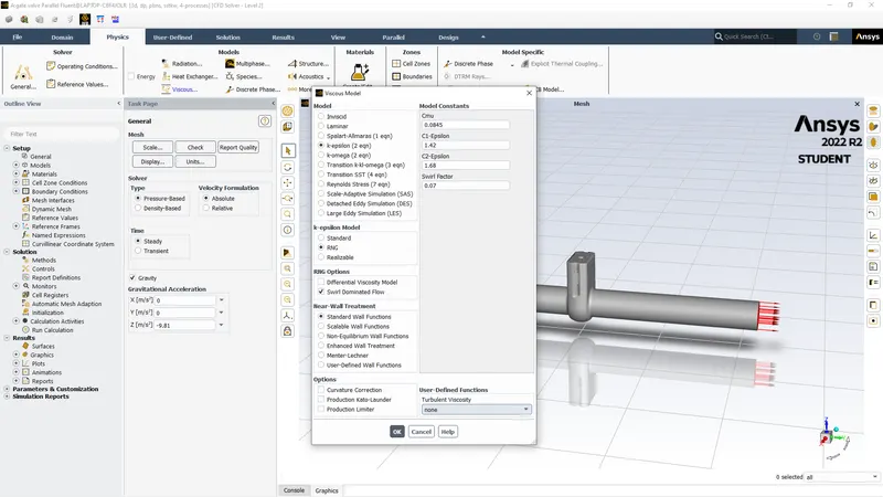
Then we copy the material data for water from fluent database.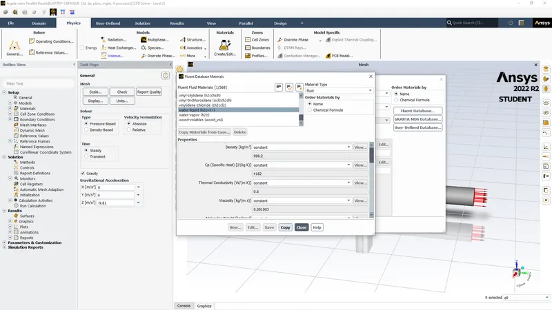
Then in cell zone we change fluid from air to water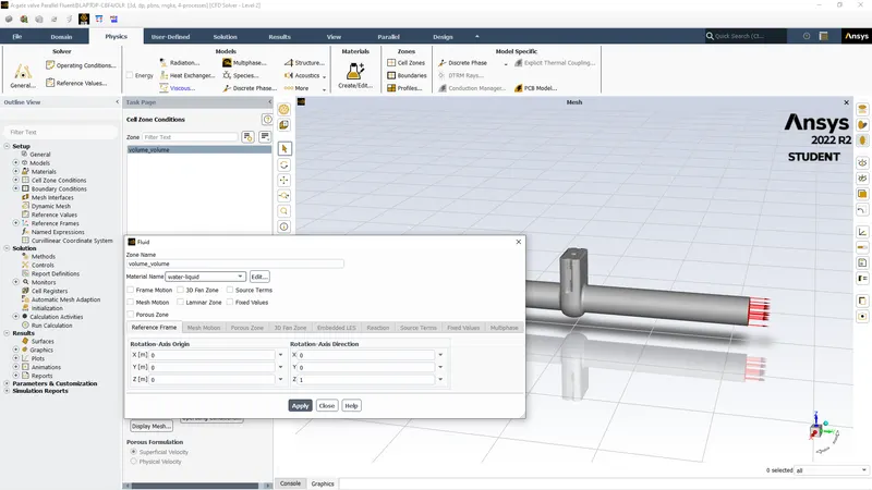
Then for boundary condition in inlet we give pressure based data with 20Pa input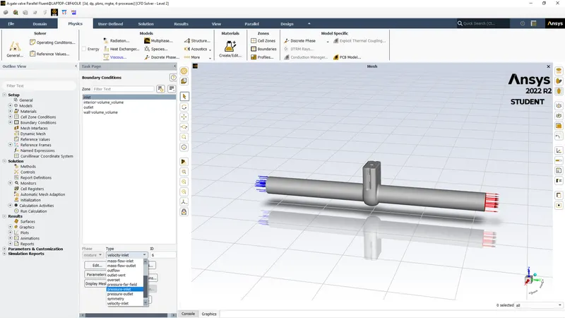
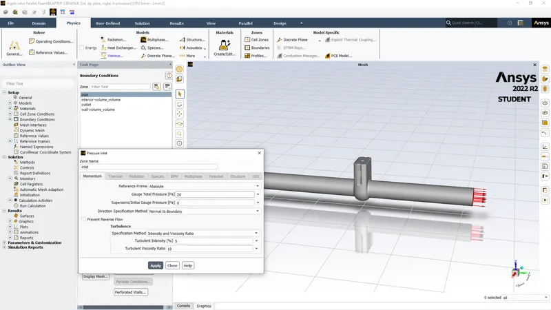
After giving all inputs we need report data for mass flow rate we create report for that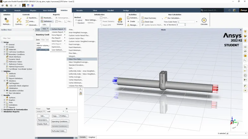
Results
CASE 1 ( 10% GATE OPEN)
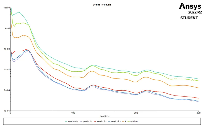
Residuals
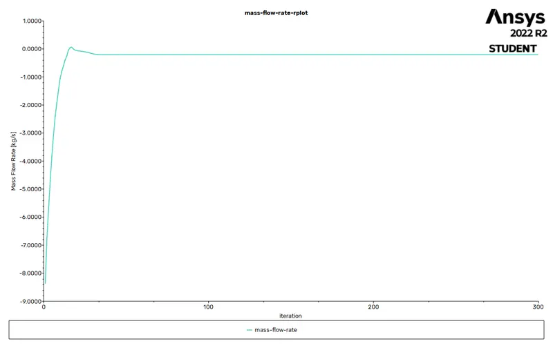
Mass flow rate
Velocity vector and contour
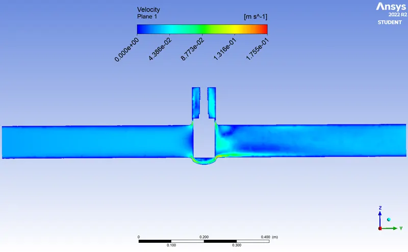
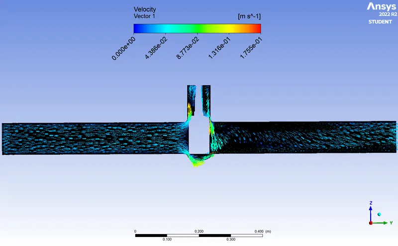
CASE 2 ( 20% GATE OPEN)
Residual
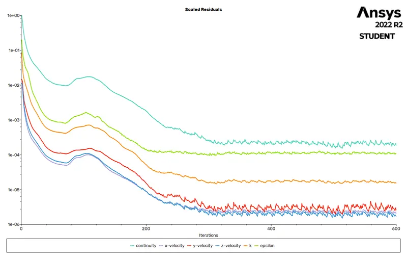
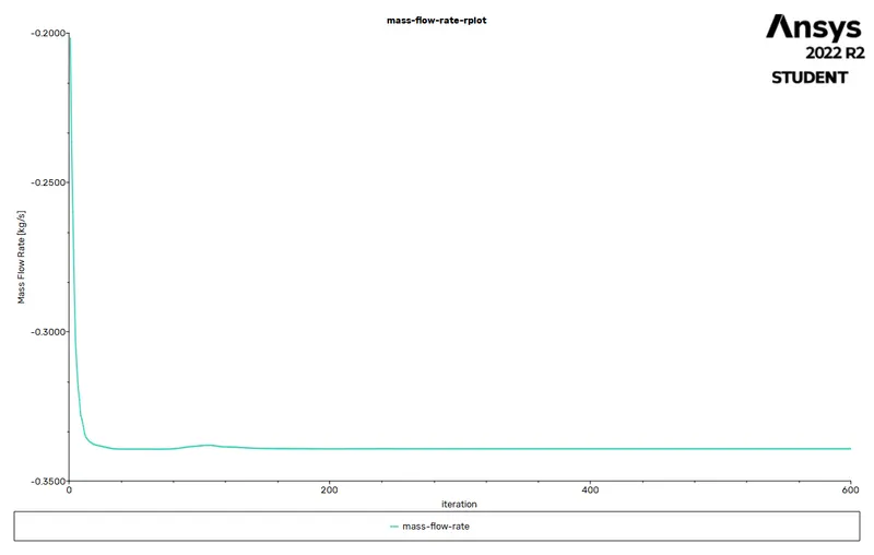
Mass flow rate
Velocity vector & contour
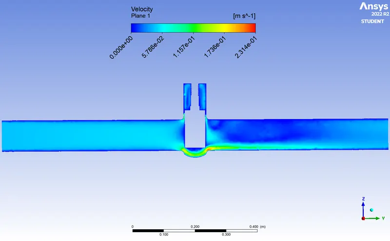
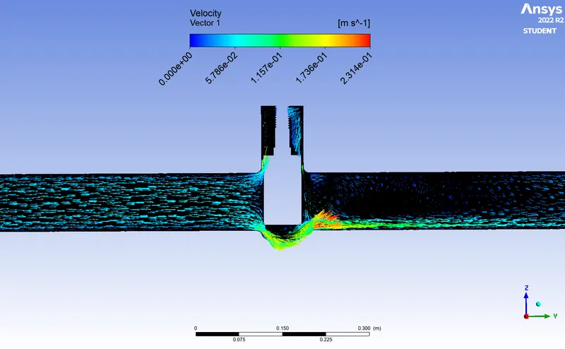
CASE 3 ( 30% GATE OPEN)
Residual
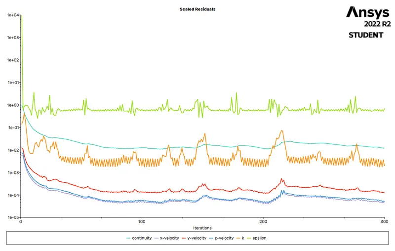
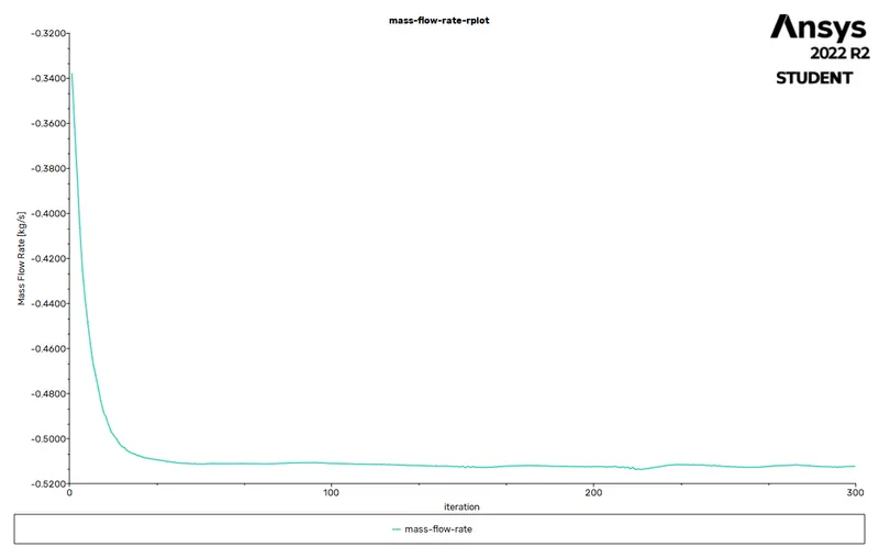
Mass flow rate
Velocity vector and contour
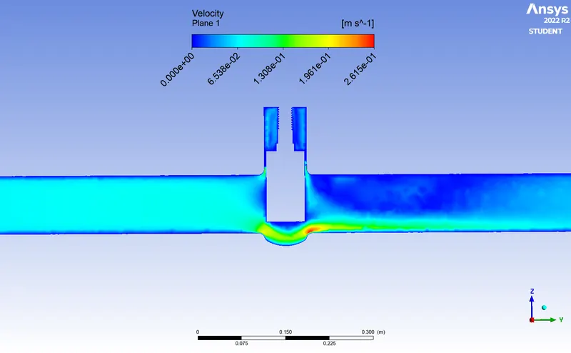
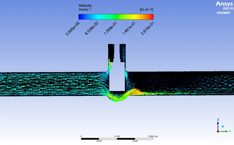
CASE 4 ( 40% GATE OPEN)
Residual
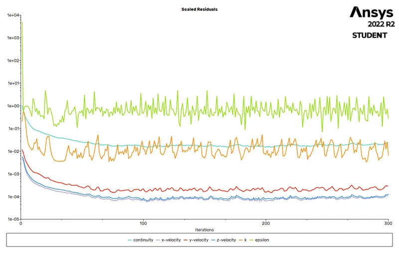
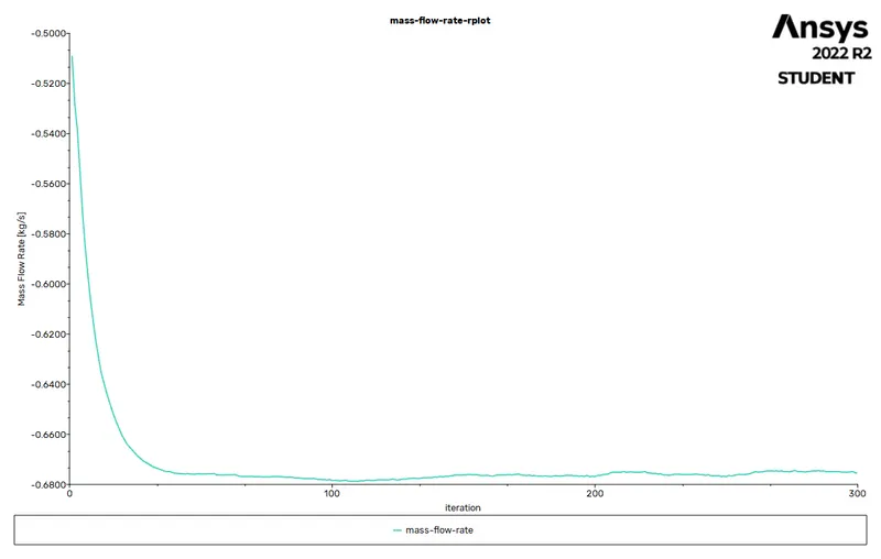
Mass flow rate
Velocity vector & contour
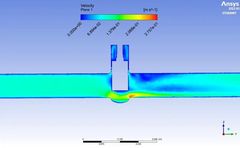
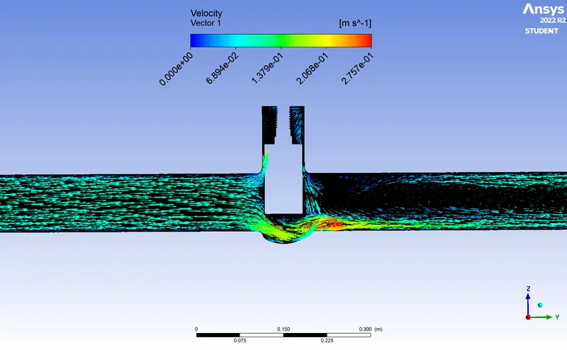
CASE 5 (50% GATE OPEN)
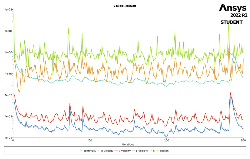
Residual
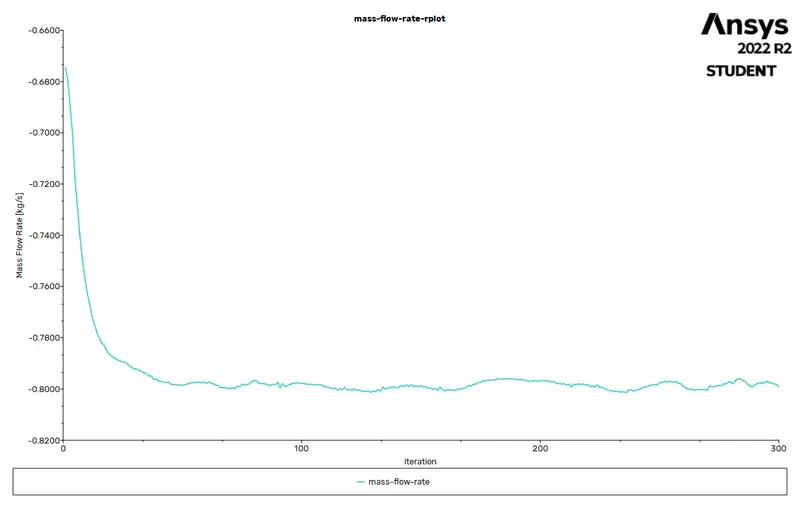
Mass flow rate
Velocity vector & vector
CASE 6 (60% GATE OPEN)
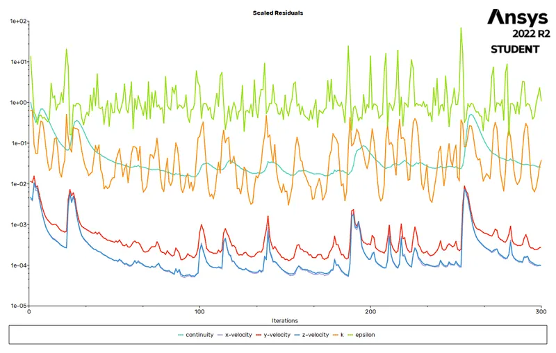
Residual
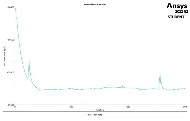
Mass flow Rate
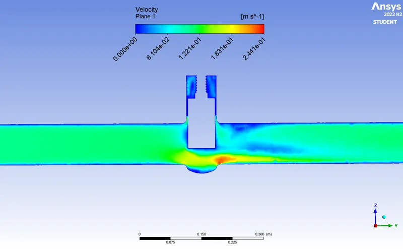
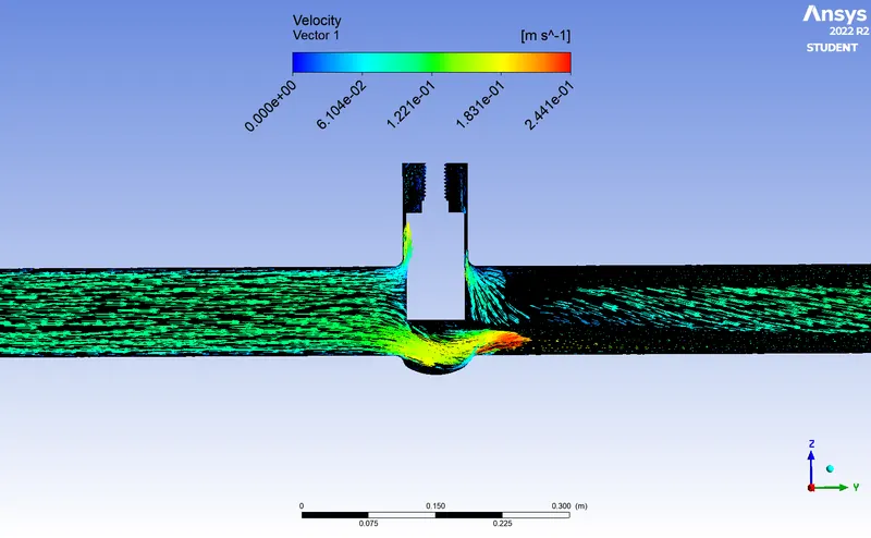
Velocity vector & contour
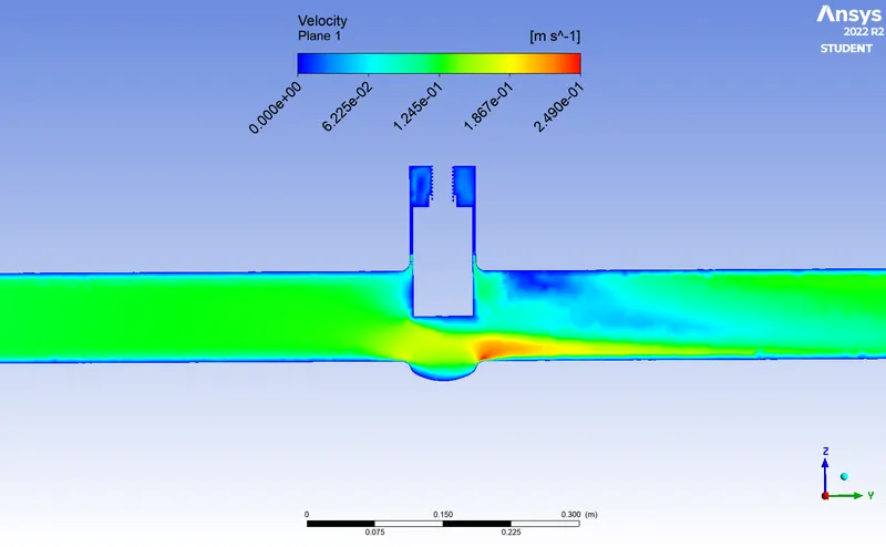
CASE 7 (70% GATE OPEN)
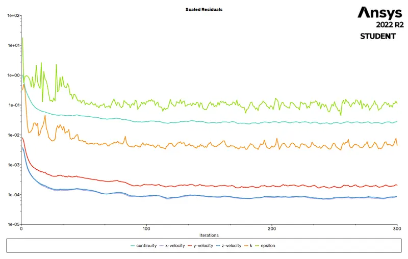
Residual
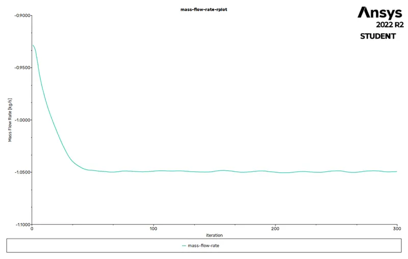
Mass flow rate
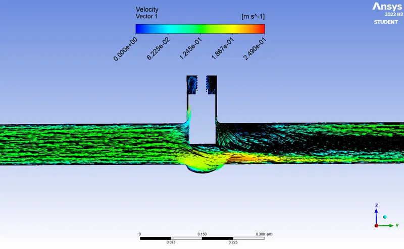
Velocity vector & contour
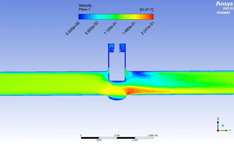
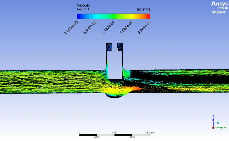
CASE 8 (80% GATE OPEN)
Residual
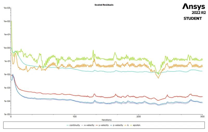
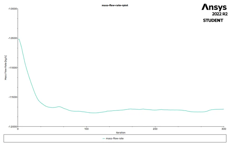
Mass flow rate
 Velocity contour & vector
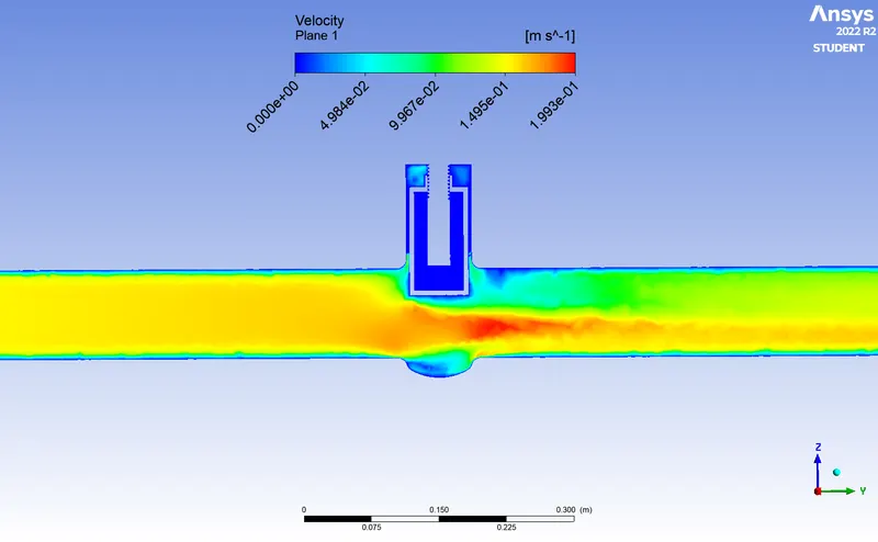
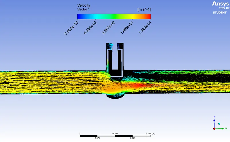
CONCLUSION
we know that
`Kv= Q * sqrt((SG)/(triangleP)`
where
Q= rate of flow(in m3/s)
SG= specific gravity(1 for water)
`triangleP`= pressure drop(in pascal)
kv= cv*0.865
Cv=Kv/0.865
| LIFT IN (mm) | FLOW RATE(Q)KG/S | PRESSURE DROP(Pa) (Inlet - outlet pressure) |
FLOW COEFFICIENT(Cv) | FLOW FACTOR(Kv) |
| 10 | 0.20625 | 19.63 | 53.81 | 46.55 |
| 20 | 0.33921 | 19.03 | 89.8 | 77.75 |
| 30 | 0.51224 | 17.78 | 140.45 | 121.48 |
| 40 | 0.67556 | 16.17 | 194.21 | 167.9 |
| 50 | 0.79923 | 14.6 | 241.8 | 209.16 |
| 60 | 0.92491 | 12.83 | 298.5 | 258.21 |
| 70 | 1.0493 | 10.84 | 368.5 | 318.75 |
| 80 | 1.1705 | 8.54 | 462.85 | 400.36 |
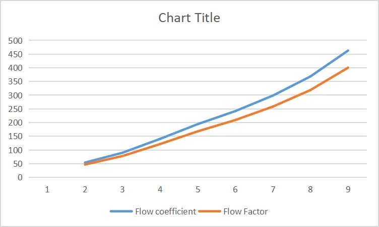
Flow factor & coefficient graph
- Mass flow rate gradually increases as the lift of gate disc is increased.
- Negative mass flow rate is due to mass exiting from body.
- The variation of flow coefficient and flow factor with the opening of the valve is studied using parametric.
- Parametric study is time reducing option when studying the effects of changes of certain parameters of system.
- Flow factor and coefficient increses as mass flow rate through valve increses.
- Flow coefficient plays important role in selection of valve sizing so calculating is important factor.
- Flow coefficient also helps in computing the efficiency of system and effect of pressure on the system.