Week 9 - Parametric study on Gate valve.
Aim:
To perform a parametric study on the gate valve simulation by setting the opening from 10 % to 80%.
Objective:
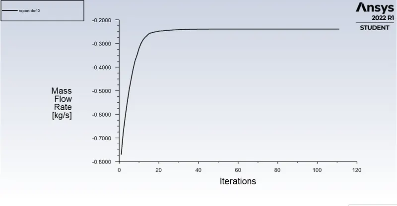
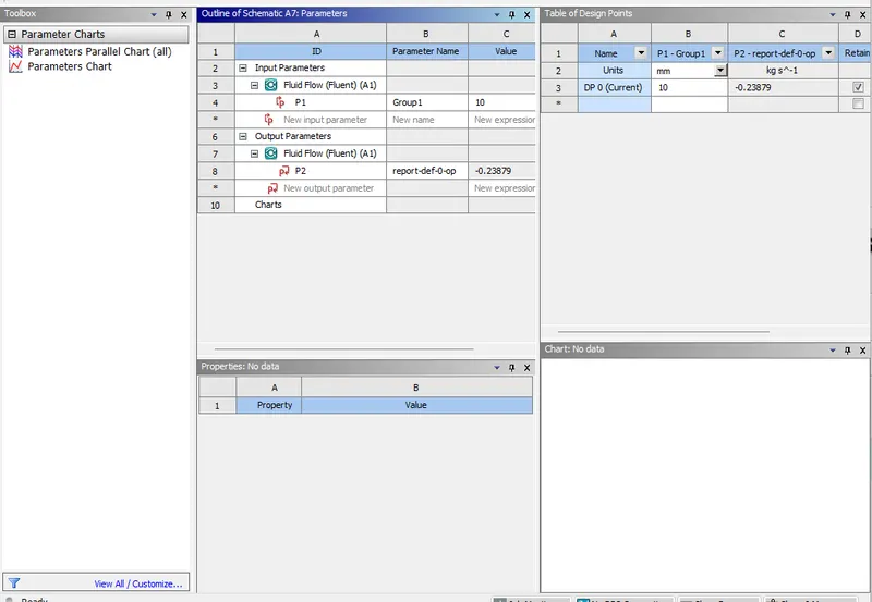
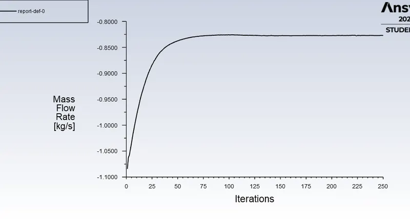
- Obtain the mass flow rates at the outlet for each design point.
- Calculate the flow coefficient and flow factor for each opening and plot the graph.
- Discuss the results of the mass flow rate and flow coefficient.
Theory:
Introduction:
Gate valves are designed for fully open or fully closed service. They are installed in pipelines as isolating valves and should not be used as control or regulating valves. Operation of a gate valve is performed doing an either clockwise to close (CTC) or clockwise to open (CTO) rotating motion of the stem. When operating the valve stem, the gate moves up- or downwards on the threaded part of the stem.
Where are gate valves used?
Gate valves are often used when minimum pressure loss and a free bore is needed. When fully open, a typical gate valve has no obstruction in the flow path resulting in a very low pressure loss, and this design makes it possible to use a pipe-cleaning pig. A gate valve is a multiturn valve meaning that the operation of the valve is done by means of a threaded stem. As the valve has to turn multiple times to go from open to closed position, the slow operation also prevents water hammer effects.
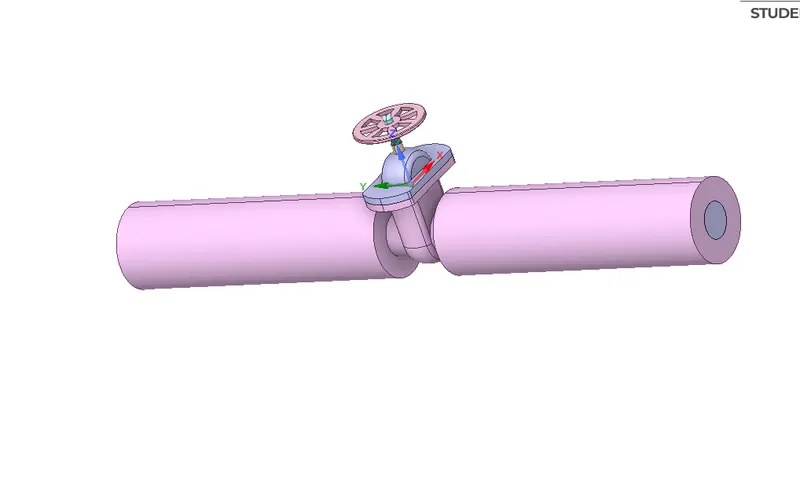
A Gate Valve, or Sluice Valve, as it is sometimes known, is a valve that opens by lifting a round or rectangular gate/wedge out of the path of the fluid. The distinct feature of a gate valve is the sealing surfaces between the gate and seats are planar. The gate faces can form a wedge shape or they can be parallel. Gate valves are sometimes used for regulating flow, but many are not suited for that purpose, having been designed to be fully opened or closed. When fully open, the typical gate valve has no obstruction in the flow path, resulting in very low friction loss and when the gate valve is closed there are many obstructions in the flow path which in turn produces high frictional losses. To avoid or minimize the frictional losses study of stress distribution in the parts of the gate valve is done before manufacturing of gate valve. We have selected a 4 1/16” Gate Valve for the analysis of stress distribution. The main reason to choose the gate valve is to carry out the basic analysis process of all the components. It is tedious and great work for a designer to make the accurate stress distribution of any mechanical component. So some deficiencies in the design of parts are left. To overcome these deficiencies computer software’s used. Analysis and optimization done by using analysis software give greater accuracy and also minimize the time of the designer. Slab Gate Valve Due to the various environments, system fluids, and system conditions in which flow must be controlled, a large number of valve designs have been developed. A basic understanding of the differences between the various types of valves, and how these differences affect valve function, will help ensure the proper application of each valve type during design and the proper use of each valve type during operation.
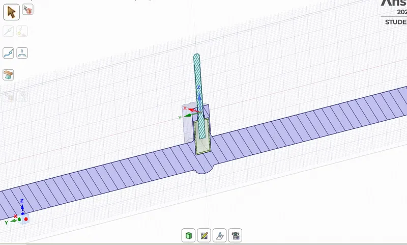
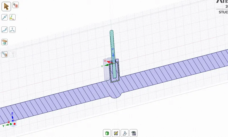
Geometry:
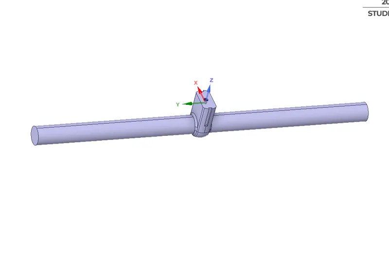
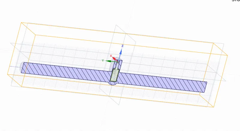
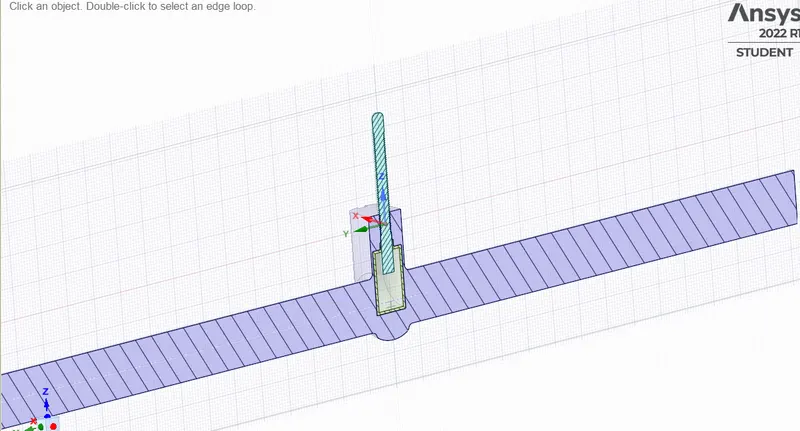
Valve Opening at 10%:
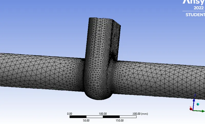
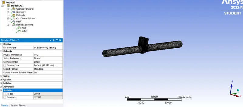
Meshing:
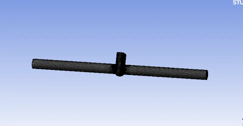
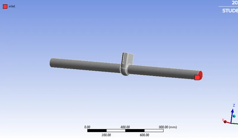
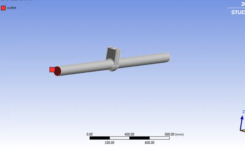
Providing names on inlet and outlet:
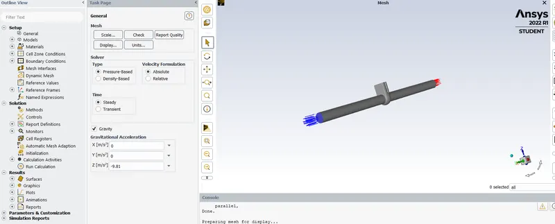
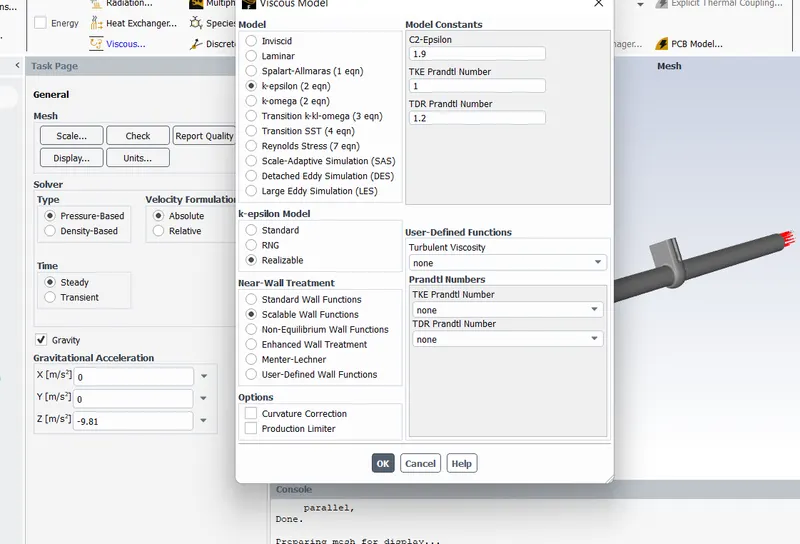
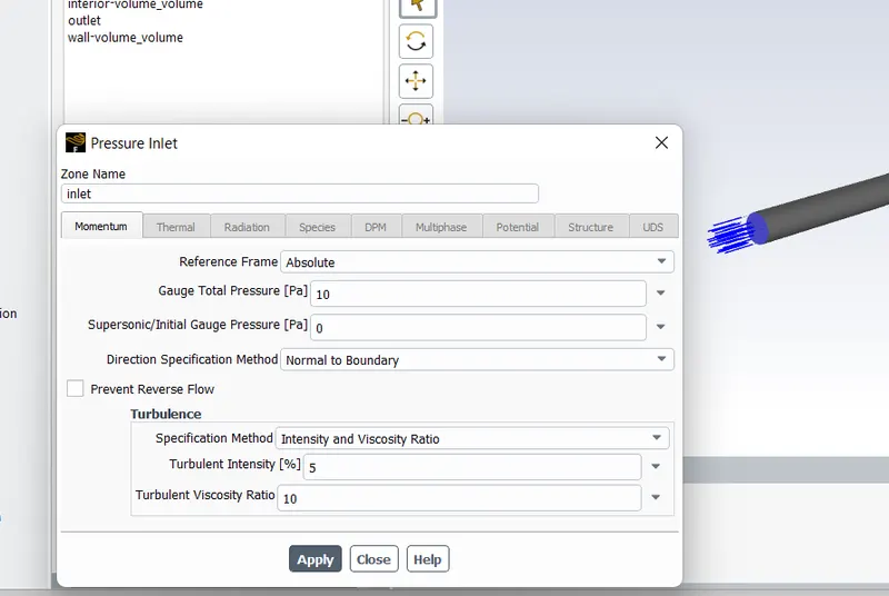
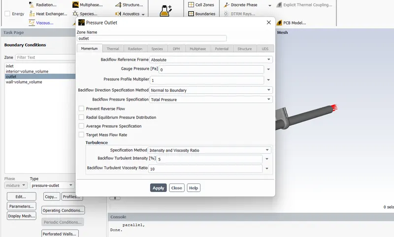
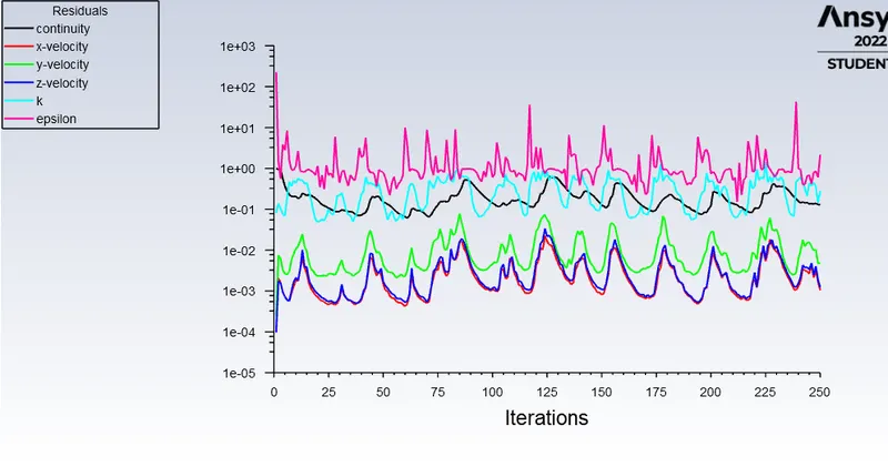
Setup:
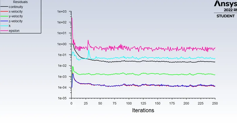
Preprocessing:
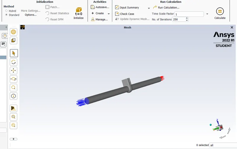
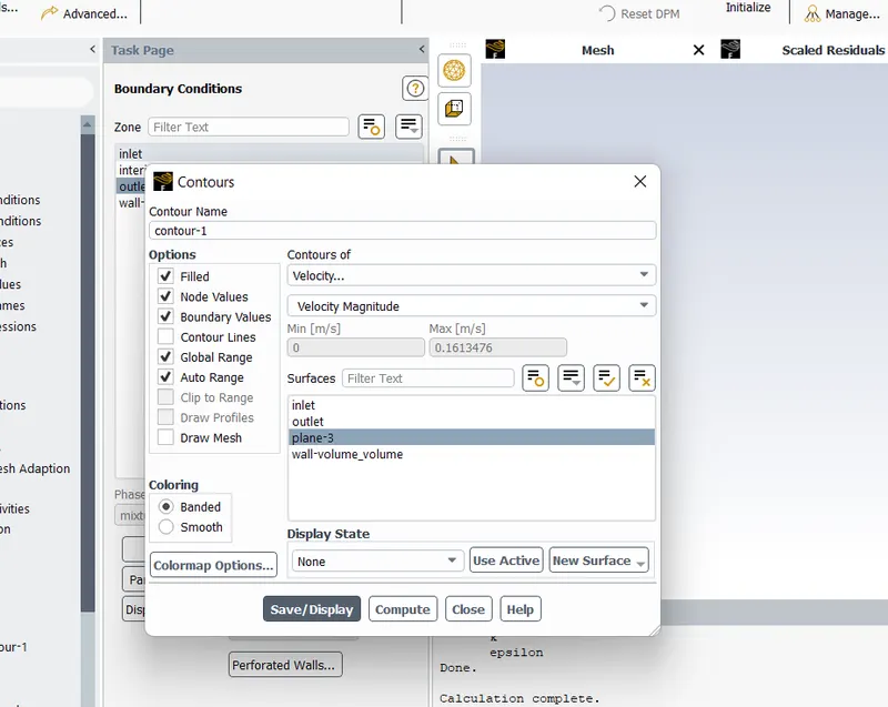
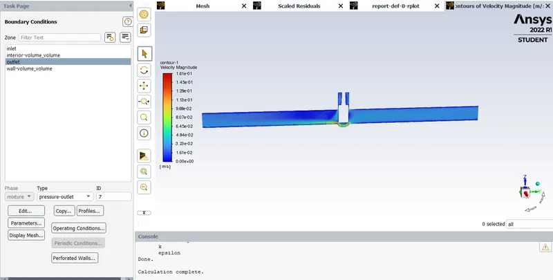
RESULT:
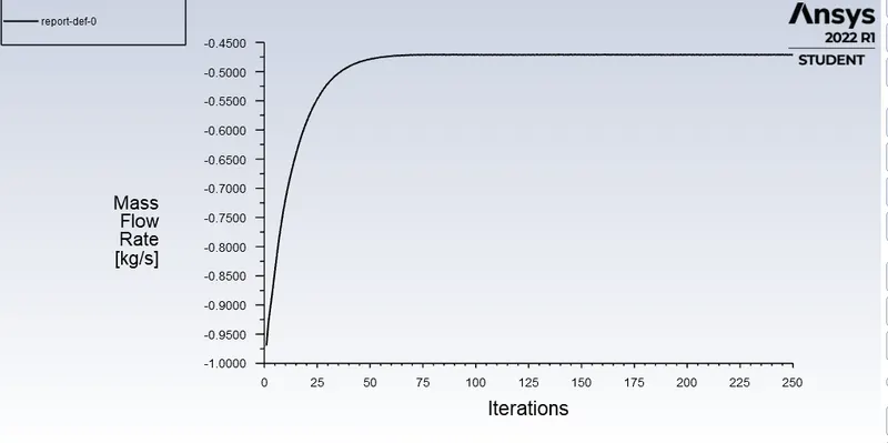
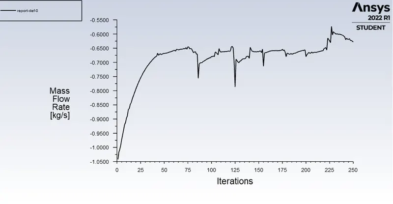
Mass flow rate:
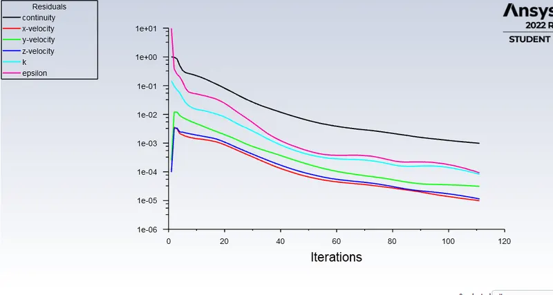
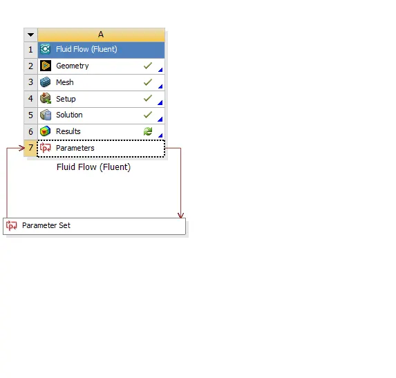
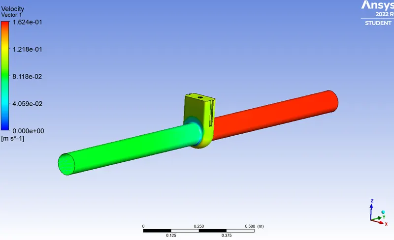
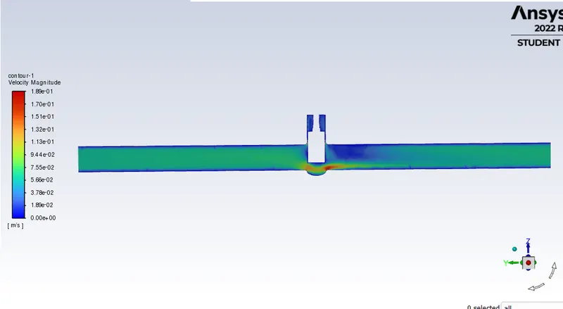
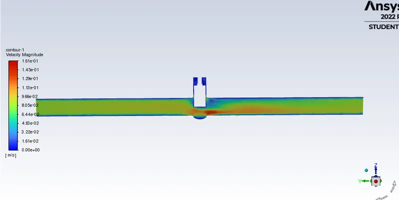
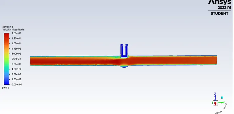
Results:
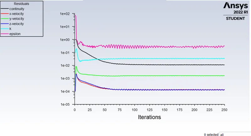
Parameter charts:
opened at 30%:
Opening at 50%:
opening at 80%:
Conclusion:
Hence we have obtained the different valve presentations of fluid flow and velocity contours as well as the mass flow rate at the different openings of the valve from 10% to 80%.
We have noticed that at different levels of the valve the fluids react differently with shows that fluid pressure and velocity can vary at different levels of the valve.