Week 9 - Parametric study on Gate valve.
Methodology :
The methodology we are applying here is first of all we have to Activate parameters at a appropriate points throughout the simulation in order to get desired output.
And the second thing is that we have to take care of is to Adapt fluid volume to changing solid geometry.
Introduction : -
Gate Valve - A gate valve is also known as a sluice valve , is a valve that opens by lifting a barrier (gate) out of the path of the fluid. Gate valve require very little space along the pipe axis and hardly restrict the flow of fluid when the gate is fully opened. The gate faces can be parallel but are most commonly wedge -shaped (in order to be able to apply pressure on the sealing surface).
Application of Gate Valve -
- Gate valve are used to shut off the flow of liquids rather than flow regulation. When fully open, the typical gate valve has no obstruction in the flow path, resulting in very low flow resistance. The size of the open flow path generally varies in a nonlinear manner as the gate is moved. This means that the flow rate does not change evenly with stem travel. Depending on the construction, a partially open gate valve can vibrate from the fluid flow.
- Gate valves are mostly used with larger pipe diameters ( from 2" to the largest pipelines) since they are less complex to construct than other types of valves in larger sizes.
- Gates valves without an extra sealing ring on the gate or the seat are used in application where minor leaking of the valve is not an issue, such as heating circuits or sewer pipes.
Different types of gate Valves :
- Wedge Gate Valve
- Plug-Disk Gate Valve
- Subsea Gate Valve
- Knife Gate Valve
- Insider Screw Gate Valve
- Rising Stem Gate Valve
Functioning Principle :
Main component of a Gate Valve are body, seat, stem,bonnet and actuator. The main operation mechanism is very simple. When the hand wheel is turned, it rotates the fluid, which is translated into the vertical movement of a Gate Disc via threads. They are considered multi-turn valves as it makes more than one 360 degree turn to fully open/close the valve. When the Gate is lifted from the path of the flow, the valve opens and when it returns to its closed position,it seals the bore resulting in a full closure of the valve.
Parametric Study :
One of the best ways to get value out of your simulation is to do parametric analysis. With bery little marginal work a completed model can be parameterized to simulate scenarios limited only by your computational time and resources.
As you move forward in your design, you can asses the impact that changing certain parameters can have on the design. The parameters can include dimensional parameters. Parameters studies allow you to nominate parameters for evaluation, define the parameter range, specify the design constraints, and analyze the results of each parameter variation.
Modeling Approach :
Pre-Processing:
1. Importing geometry in SpaceClaims
The following geometry was imported into SpaceClaim
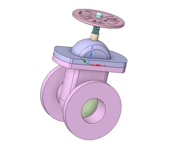
It has following components.
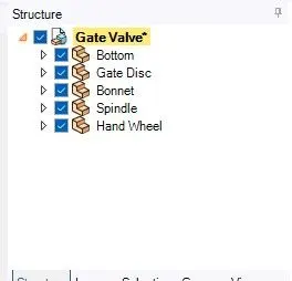
Bottom
Gate Disc
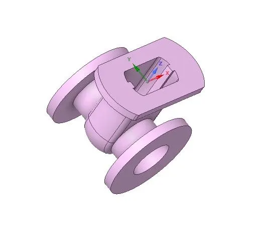
Bonnet
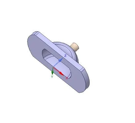
Spindle
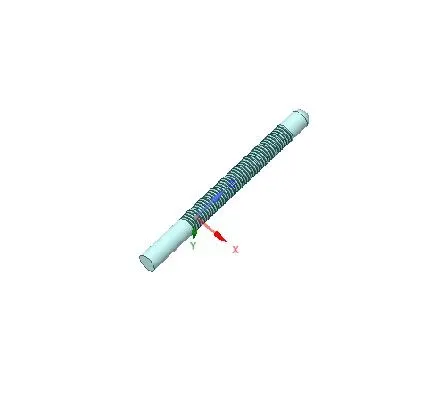
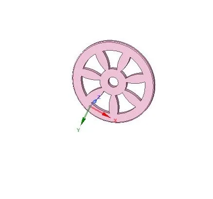
Hand Wheel
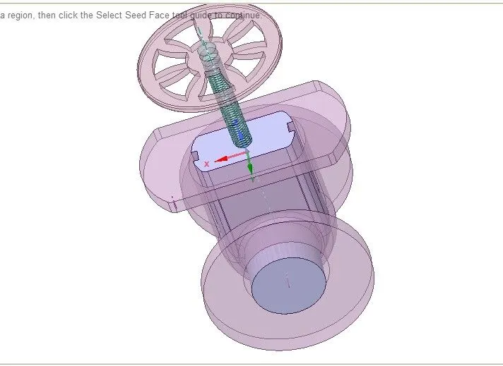
after the volume extraction the valve is going to be looks like
Meshing
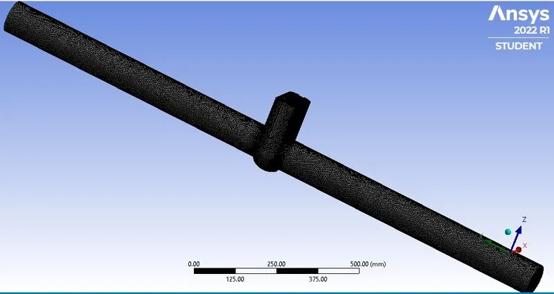
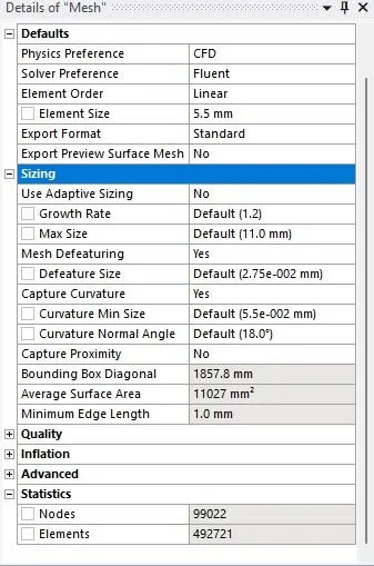
i provided mesh size is about 5.5 and you can see the results given below
Ansys Fluent
So now close the meshing window and come to the Ansys Fluent
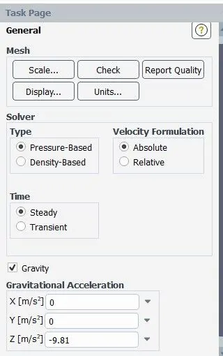
so i was used Steady , pressure-Based solver with the mark gravity in the z-direction.
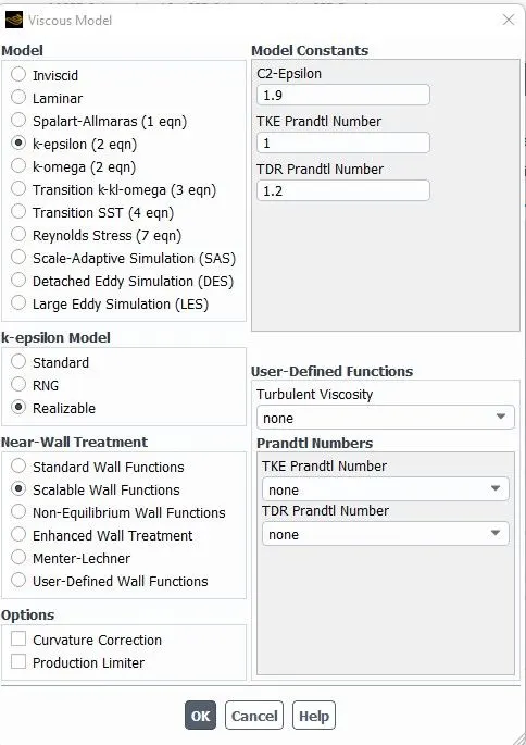
Here i am used k-epsilon with Realizable Model.
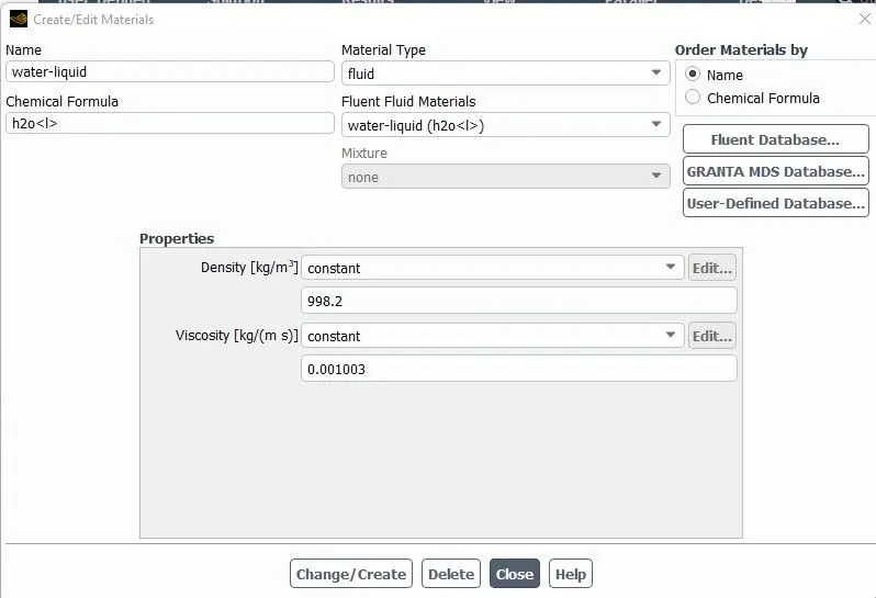
so next i am going to add the water(liquid phase) as a default material .
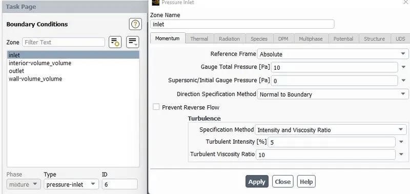
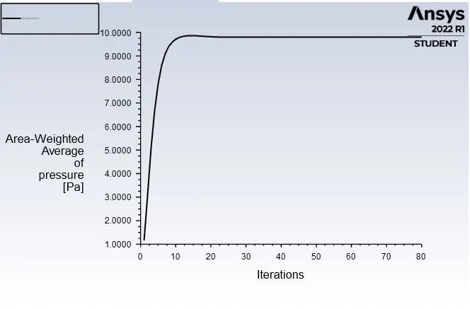
And change the inlet type from velocity to pressure based and give value of pressure is 10 pascal
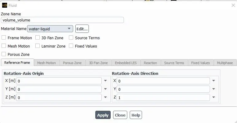
Again in the Zone name change material name from air to water-liquid and click on apply.
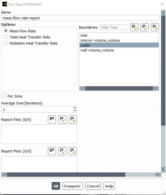
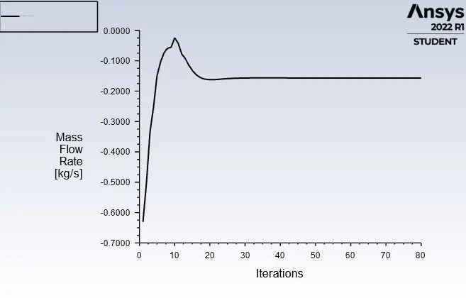
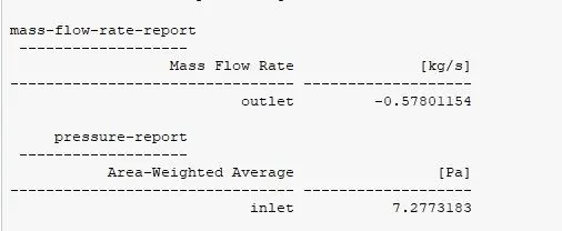
Go to the the Definition report and make the mass-flow-rate-report and i am going to choose outlet for Mass Flow Rate
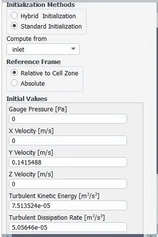
Finally , initialized the method as Standard initialization and here i am going to compute from inlet so i choosed inlet here
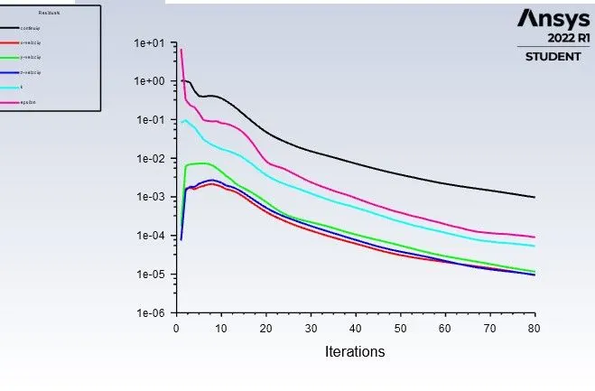
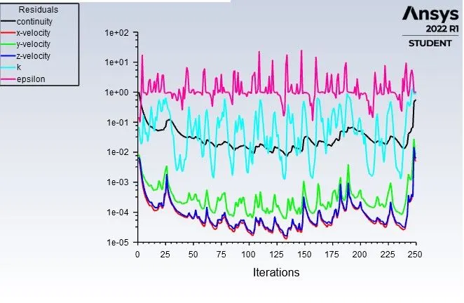
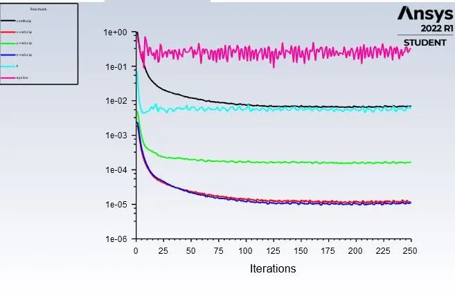
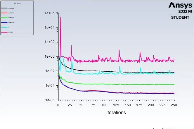
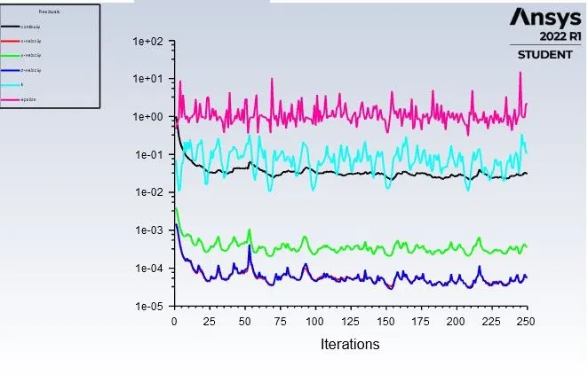
Now i am hit on the run button with 250 iteration and we will look into residuals and mass flow rate plot and after this we can see pressure and velocity contour.
so i am showing you plots of Fluent as well as plots in post-processing .
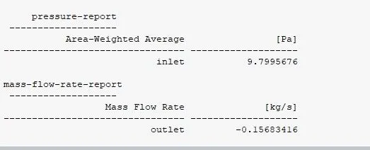
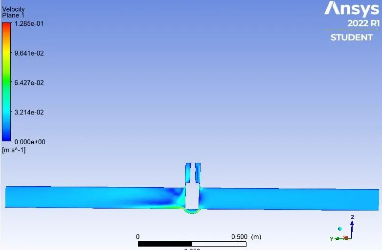
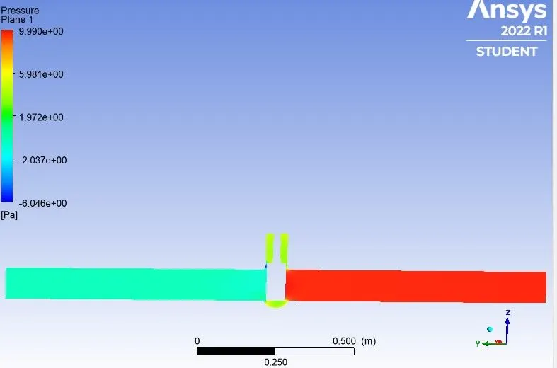
The results for the gate disc with 10mm lift can be seen below :
1. Residuals
2. Mass flow rate at outlet
3. Pressure at inlet
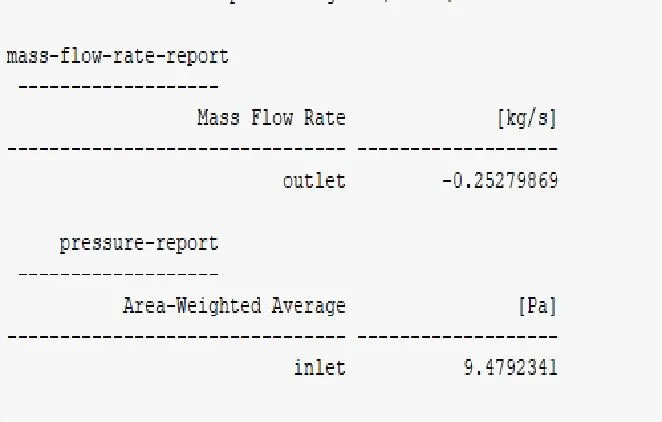
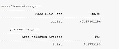
4. Values of Mass flow rate at outlet and Pressure at inlet
5. Velocity contour
6. Pressure contour
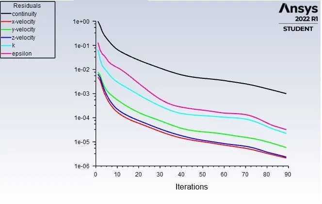
The results for the gate disc with 20mm lift can be seen below :
1. Residuals
2. Mass flow rate at outlet

3. Pressure at inlet
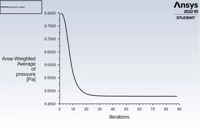
4. Values of Mass flow rate at outlet and Pressure at inlet
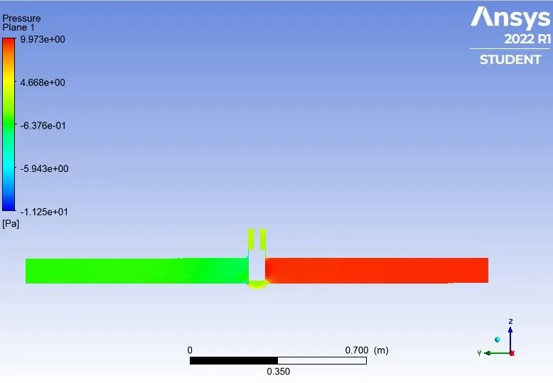
5. Pressure Contour
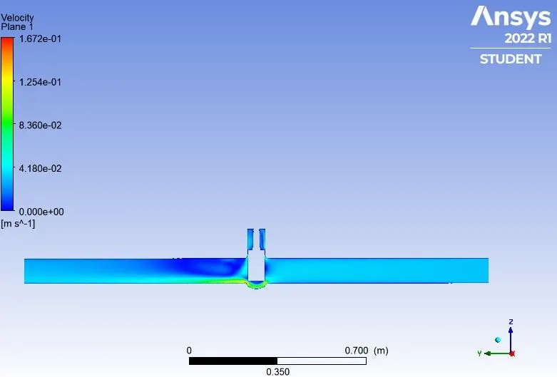
6. Velocity contour
The results for the gate disc with 30mm lift can be seen below :
1. Residuals
2. Mass flow rate plot at outlet
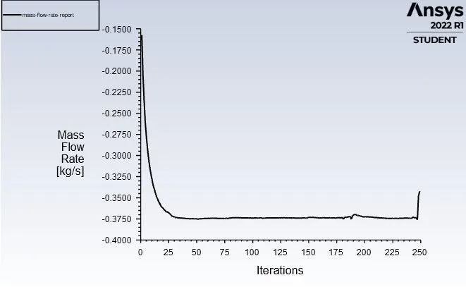
3. Pressure at inlet
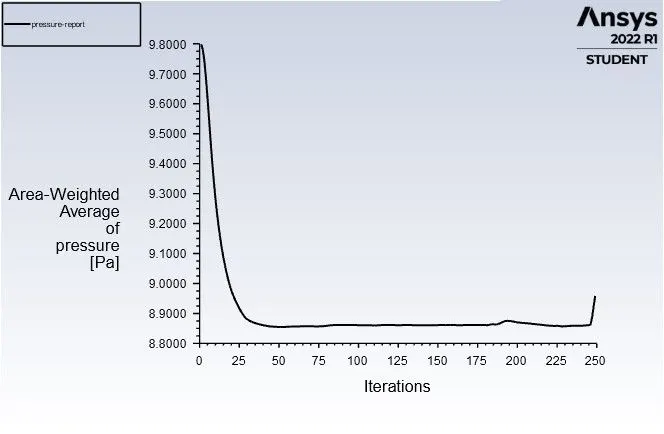
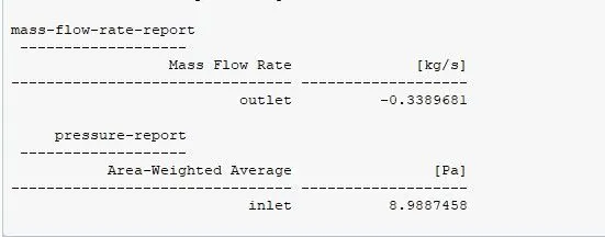
4. Values of Mass flow rate at outlet and Pressure at inlet
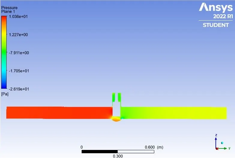
5. Pressure contour
6. Velocity contour
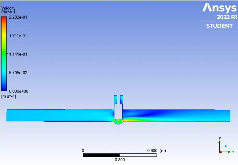
The results for the gate disc with 40mm lift can be seen below :
1. Residuals
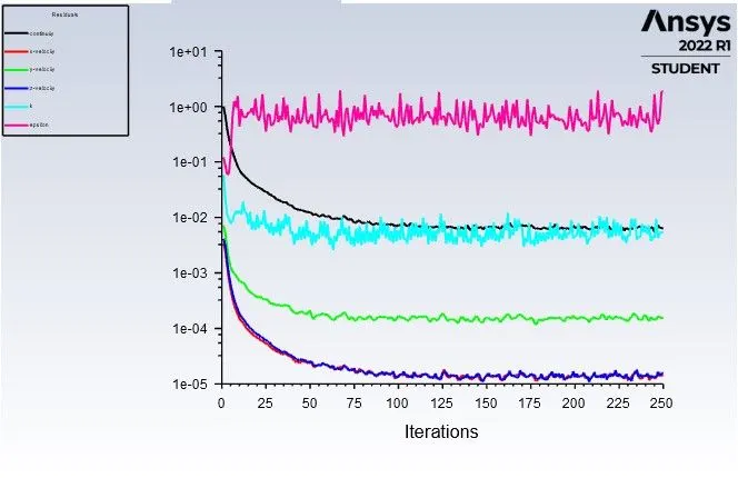
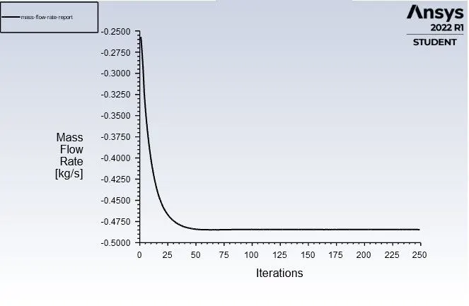
2. Mass flow rate at outlet
3. Pressure at inlet
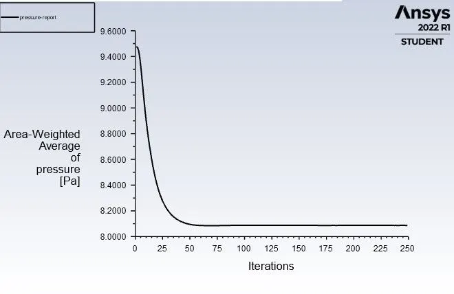
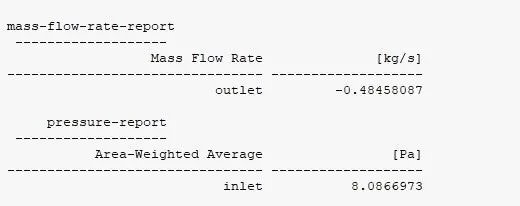
4. Values of Mass flow rate at outlet and pressure at inlet
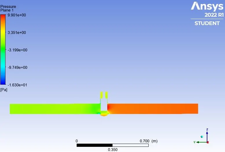
5. Pressure contour
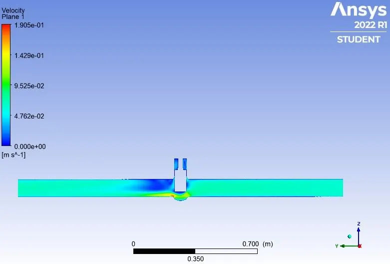
6. Velocity contour
The results for the gate disc with 50mm lift can be seen below :
1. Residuals
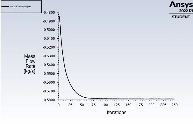
2. Mass flow rate plot for outlet
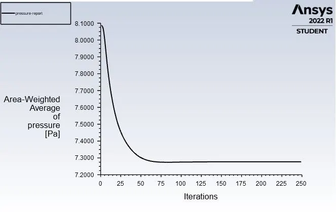
3. Pressure at inlet
4. Values of Mass flow rate at outlet and Pressure at inlet
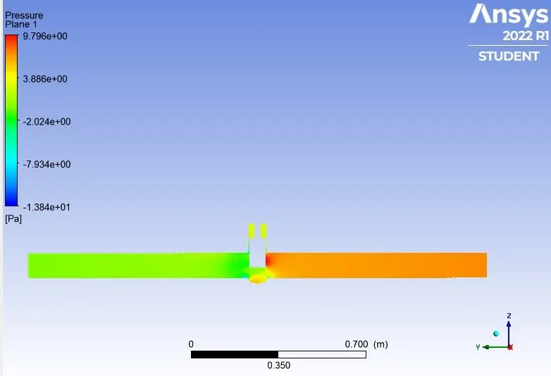
5. Pressure contour
6. Velocity contour
The results for the gate disc with 60mm lift can be seen below :
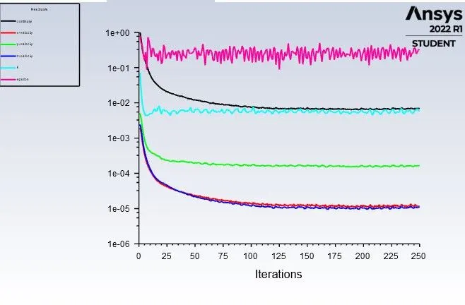
1. Residuals
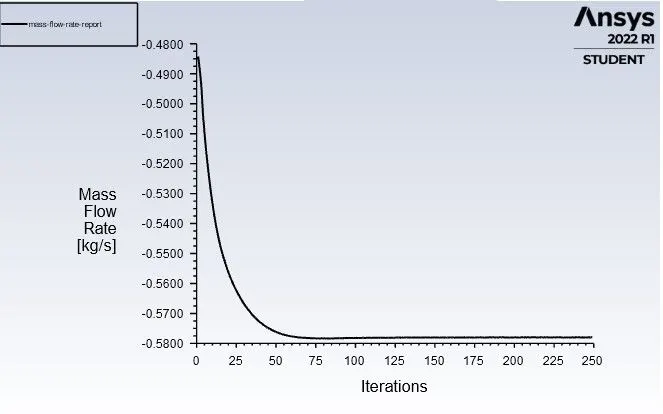
2. Mass flow rate at outlet
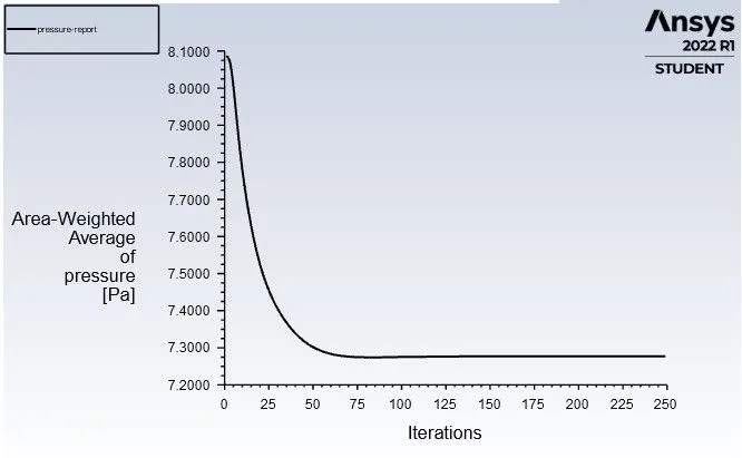
3. Pressure at inlet
4. Values of Mass flow rate at outlet and Pressure at inlet
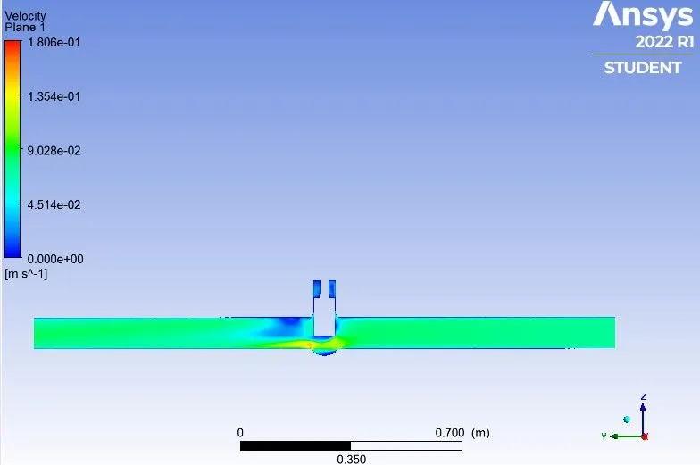
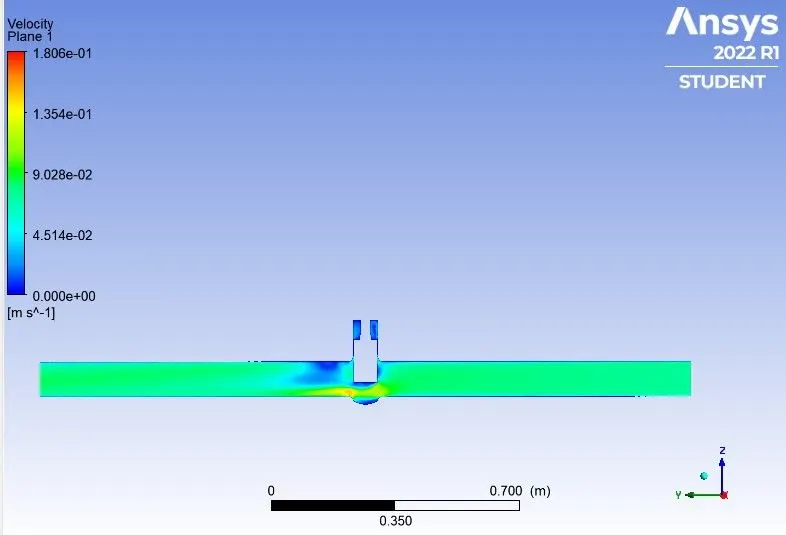
5. Velocity contour
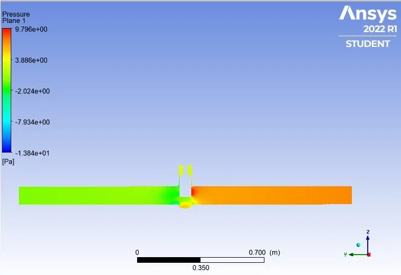
6. Pressure contour
The results for the gate disc with 70mm lift can be seen below :
1. Residuals
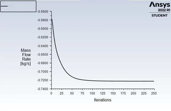
2. Mass flow rate at outlet
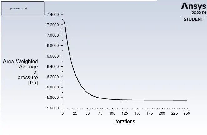
3. Pressure plot
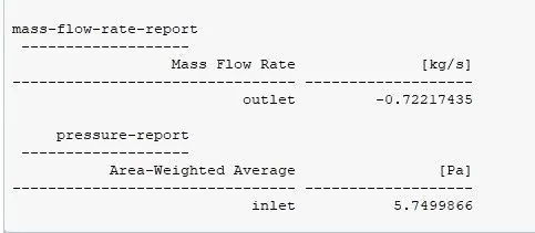
4. Values of Mass flow rate at outlet and Pressure at inlet
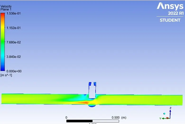
5. Velocity contour
6. Pressure plot
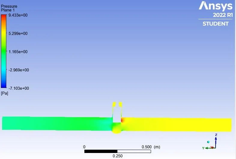
The results for the gate disc with 80mm lift can be seen below :
1. Residuals
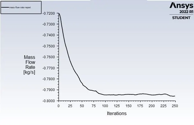
2. Mass flow rate at outlet
3. Pressure at inlet
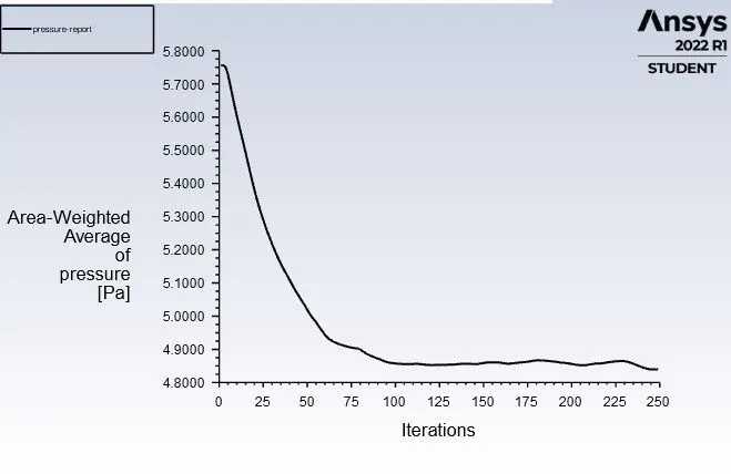
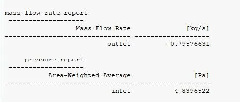
4. Values of Mass flow rate at outlet and Pressure at inlet
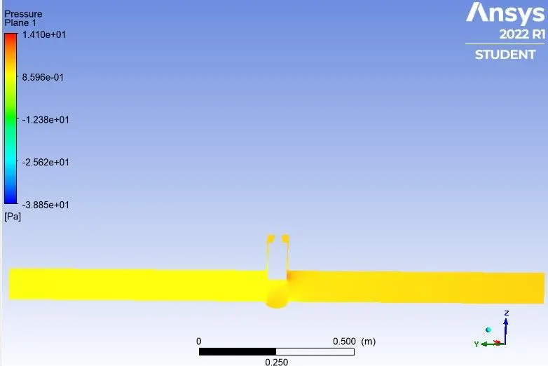
5. Pressure plot
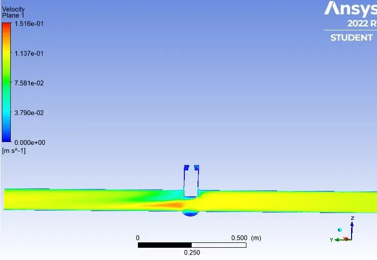
6. Velocity contour
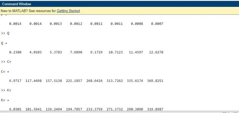
Flow Factor (Kv) :
flow rate is the flow coefficient in the metric units. It is basically defined as the flow rate in cubic meters per hour for water at the constant temperature of 16 degree celcius with the pressure drop of 1 bar across the valve.
Flow Coefficient (Cv) :
Cv is the flow coefficient in the imperial units. It is basically defined as the flow rate in US Gallons per mintue of water at a constant temperature of 60 degree farenheitand a pressure drop of 1 psi across the valve. It is used to determine the flow various conditions and to select the proper valve for the various applications.
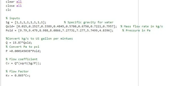
`Cv = Q sqrt({Sg}/{DeltaP})`
Q = mass flow rate in (US gallon per mintue)
Sg = Specific gravity (for water = 1)
`Delta P` = change in pressure in psi
AND
the value of flow factor
Kv = 0.865*cv
MATLAB CODE :
Values of Cv and Kv :
Conclusion :
1. The negative mass flow is due to the mass exiting the outlet.
2. With the help of the parameters the solving time and effort can be reduced drastically.
3. Differential Pressure decreases with increase in opening percentage.
4. From post-processing we can observe that velocity at midplane increases witth increase in opening percentages.
5. The mass flow rate increase as we uplift the valve .