Week 9 - Mini project - Flow over an Airfoil
AIM:
- To run steady state simulations on a NACA 2412 airfoil at different angles of attack. Calculate the drag and lift coefficients for various AOA using the time averaging method to find the optimum pain and lift force. Create the necessary contours and graphs to aid understanding.
THEORY:
1. ANGLE OF ATTACK:
- The angle of attack (AOA, or alpha) is the angle between a reference line on a body (typically the chord line of an airfoil) and the vector representing the relative motion between the body and the fluid through which it is moving in fluid dynamics. The angle of attack is formed by the body's reference line and the oncoming flow. This article focuses on the most common application, the rise of attack of a moving wing or airfoil.
- The angle of attack in aerodynamics refers to the angle formed by the chord line of a fixed-wing aircraft's wing and the vector representing the aircraft's relative motion about the atmosphere. Because a wing can twist, a chord line for the entire wing may be impossible to define, so an alternate reference line is simply defined. The chord line of the wing's root is frequently used as the reference line. Another option is to make the reference line a horizontal line on the fuselage (and also as the longitudinal axis). Some authors do not use an arbitrary chord line, but rather the zero lift axis, where zero angles of attack correspond to zero coefficient of lift by definition.
- The relationship between the angle of attack and the lift coefficient.
- A fixed-wing aircraft's lift coefficient varies with the angle of attack. Increasing the angle of attack causes the lift coefficient to increase until it reaches its maximum, at which point it decreases.
- As a fixed-wing aircraft's angle of attack increases, the separation of the airflow from the upper surface of the wing becomes more pronounced, resulting in a decrease in the rate of increase of the lift coefficient. The illustration depicts a typical curve for a cambered straight wing. Cambered airfoils are curved in such a way that they generate lift even at low negative angles of attack. At 0 degrees of attack, a symmetrical wing has no lift. The wing shape, including the airfoil section and wing planform, also influences the lift curve. A swept wing has a flatter, lower curve and a greater critical angle.
2. DRAG:
- Drag (also known as air resistance, a type of friction, or fluid resistance, another type of friction, or fluid friction) is a force acting in the opposite direction of any object moving concerning a surrounding fluid. This can occur between two fluid layers (or surfaces), as well as between a fluid and a solid surface. Drag force is velocity dependent, unlike other resistive forces such as dry friction, which are nearly independent of velocity.
a. Drag force:
- Drag force is proportional to velocity in a laminar flow and velocity squared in a turbulent flow. Even though viscous friction is the ultimate cause of drag, turbulent drag is not affected by viscosity. Drag forces always reduce fluid velocity when compared to a solid object in the fluid's path.

where,
- Fd is the drag force,
 is the density of the fluid,
 is the speed of the object relative to the fluid,
 is the cross-sectional area,
 and is the drag coefficient
b. Drag coefficient:
- The drag coefficient (c d) is a dimensionless quantity used to quantify an object's drag or resistance in a fluid environment such as air or water. It is used in the drag equation to indicate that an object will have less aerodynamic or hydrodynamic drag if the drag coefficient is lower. The drag coefficient is always linked to a specific surface area.
3. LIFT:
- A fluid flowing around the surface of an object exerts a force on it. Lift is the component of this force that is perpendicular to the direction of the oncoming flow. In contrast, the drag force is the component of the force that is parallel to the flow direction. Lift is typically applied in an upward direction to counteract the force of gravity, but it can be applied in any direction at right angles to the flow.
a. Lift co-efficient:
- The lift coefficient (CL) is a dimensionless coefficient that relates the lift generated by a lifting body to the fluid density surrounding the body, the fluid velocity, and a reference area. A foil or a complete foil-bearing body, such as a fixed-wing aircraft, is a lifting body. CL is determined by the body's angle to the flow, Reynolds number, and Mach number. The section lift coefficient cl describes the dynamic lift characteristics of a two-dimensional foil section with the foil chord replacing the reference area.

where,
L is the lift force,
S is the relevant surface area and
q is the fluid dynamic pressure, in turn, linked to the fluid density,
u- flow speed.
A. CASE SETUP:
1. Using the coordinates provided in the.DAT file for the NACA 2412 Airfoil, create the airfoil in converge using the Geometry creation tools.
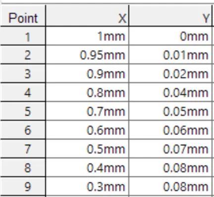
2. Create points according to the the.DAT file, join the dots with triangles, and offset the geometry to create a 3D airfoil.
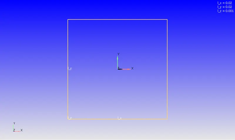
3. Construct a wind tunnel with 3x from the inlet to the outlet and 2x on top and bottom, where x is the chord length (airfoil length).
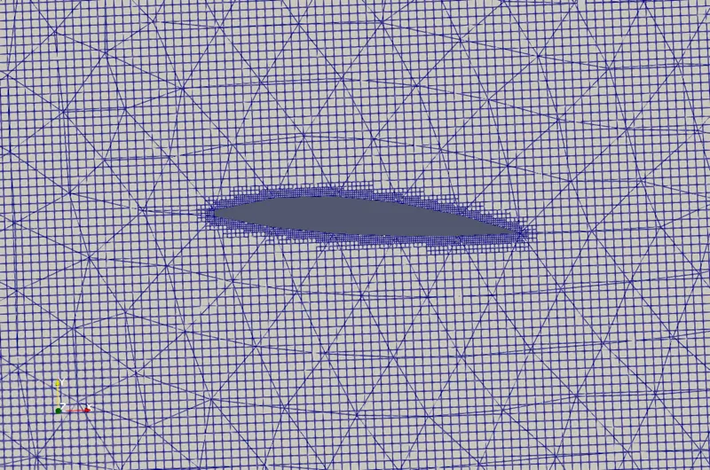
4. Connect the tunnel vertices to the airfoil and delete the airfoil's internal faces to keep it hollow for external airflow simulations.
B. CASE SETUP:
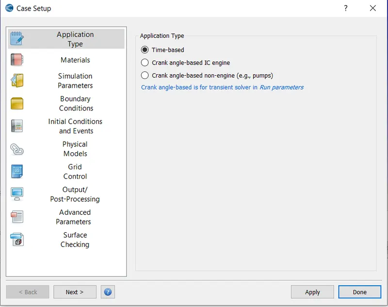
- Simulation type.
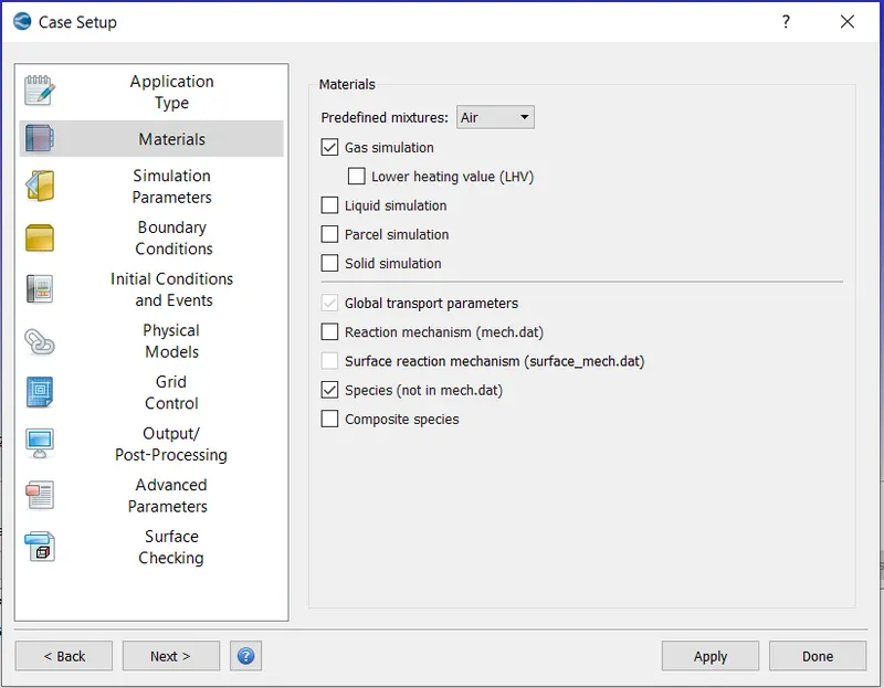
- Material:
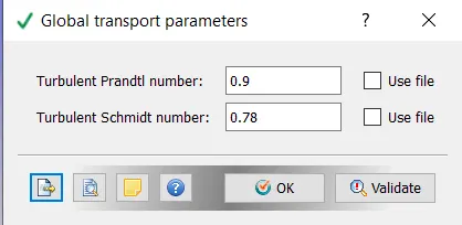
- Global Transport Parameters:
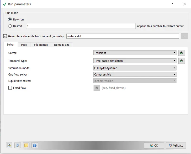
- Run parameters;
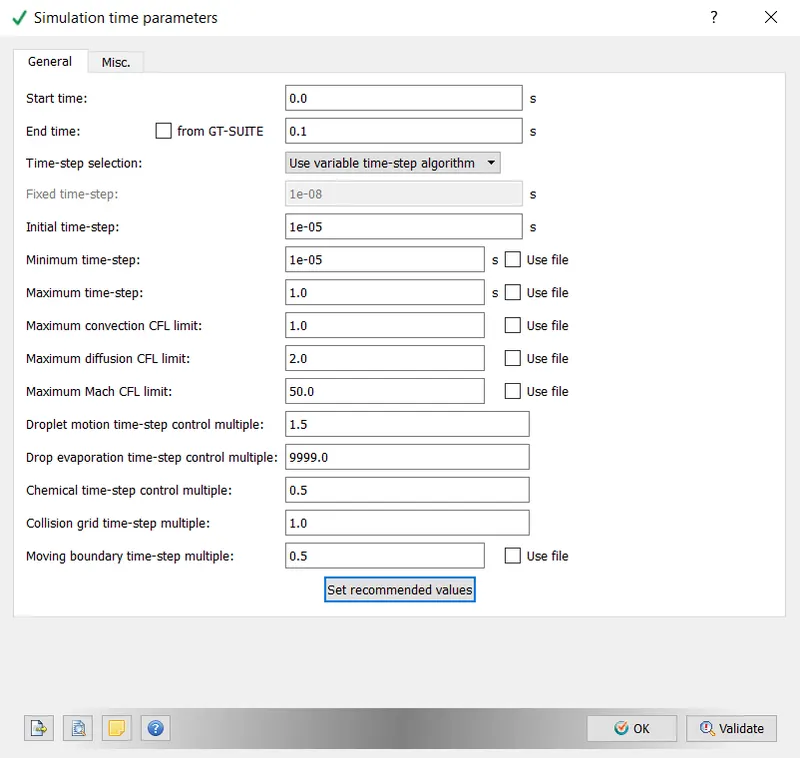
- Simulation Time parameters:
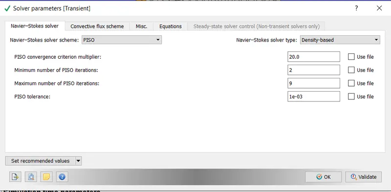
- Solver parameters:
INLET VELOCITY:
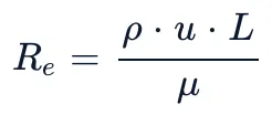
For 200000 Reynolds Number
where,
rho = 1.184 kg/m^3
L = 0.2 m
Re = 200000
mu = 0.0000186 kg/(m.s)
So, u = 15.7 m/s
The following table provides the detail of the inlet velocity for different angles of attack.
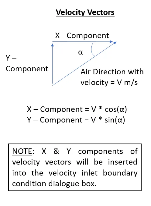
| AOA (degree) | Desired Velocity (m/s) | X - Velocity (m/s) | Y - Velocity (m/s) |
| 1 | 15.7 | 15.6976 | 0.2740 |
| 5 | 15.7 | 15.6403 | 1.3683 |
| 10 | 15.7 | 15.4615 | 2.7263 |
| 15 | 15.7 | 15.1650 | 4.0635 |
Setup Procedure of Angle of Attack = 1 degree.
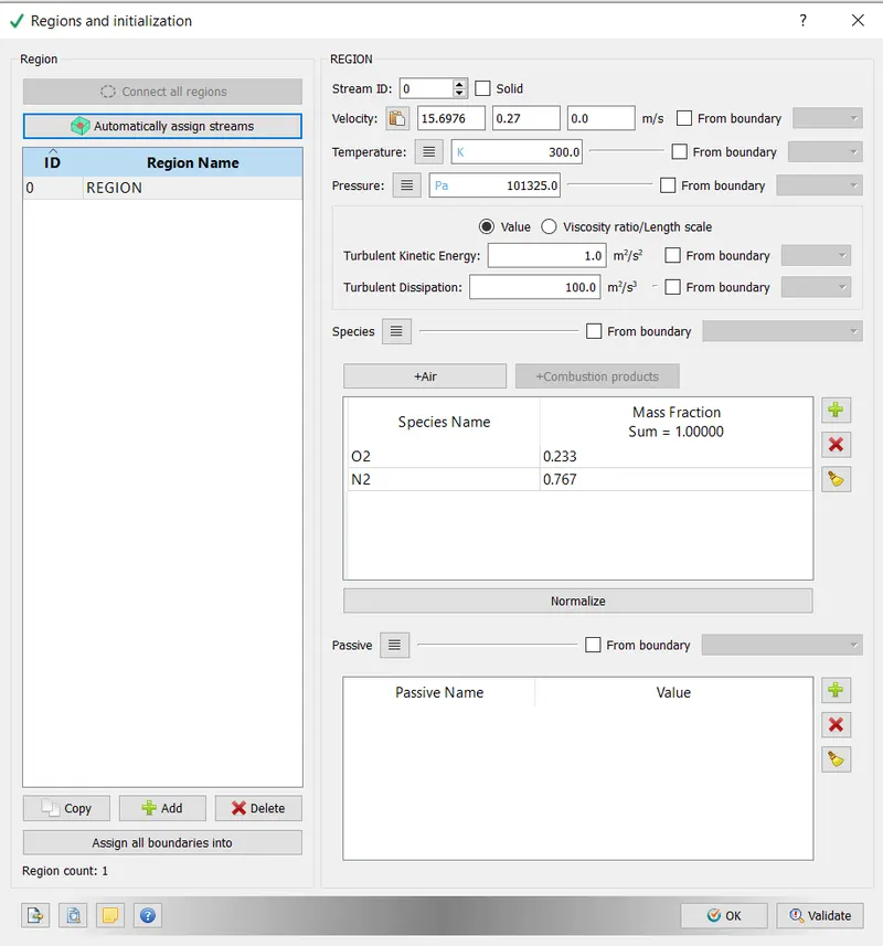
- REGIONS AND INITILIZATATION:
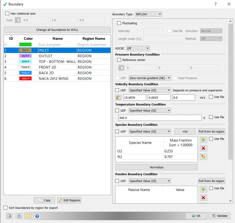
x & y velocity for the 1-degree angle of attack has been inserted from the above table.
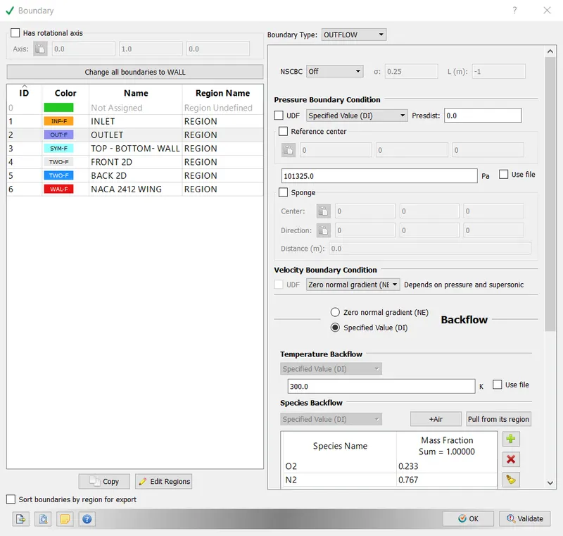
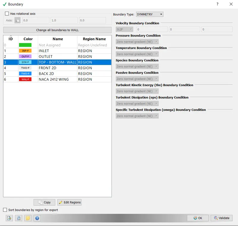
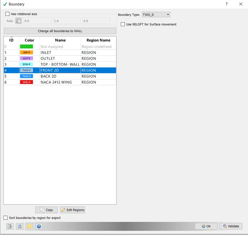
- Boundary conditions:
INLET:
OUTLET:
- Top- Bottom:
- Front 2D:
- Back 2D:
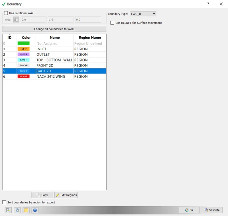
- NACA 2412 AIRFOIL:
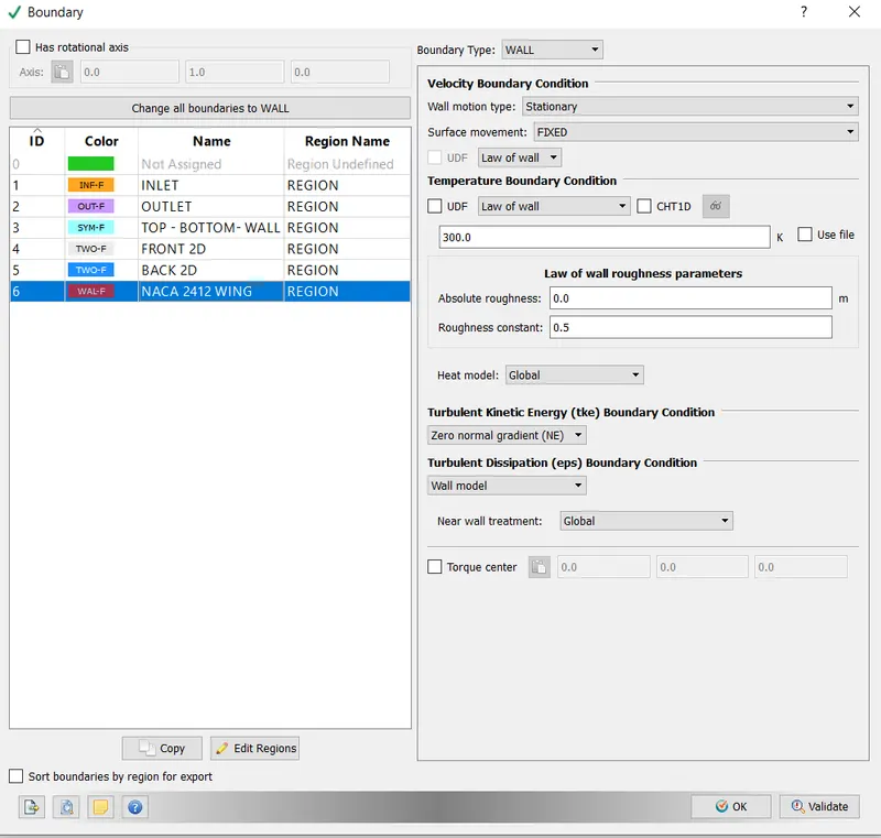
- Turbulence model:
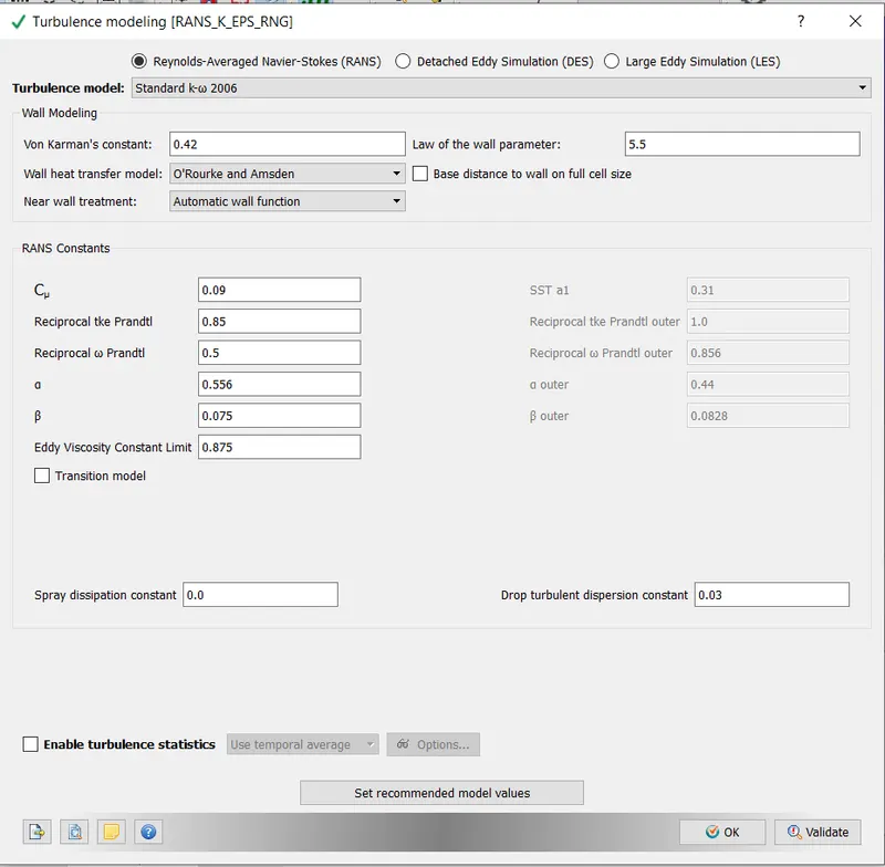
- GRID:
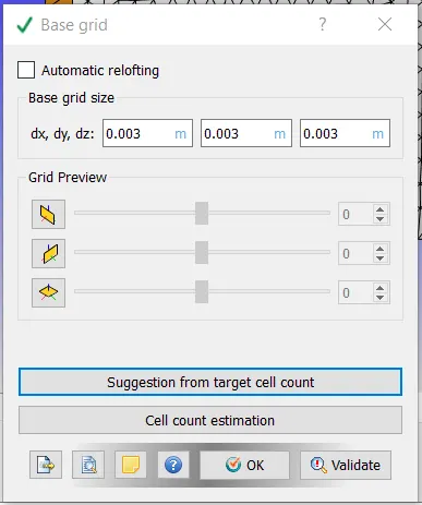
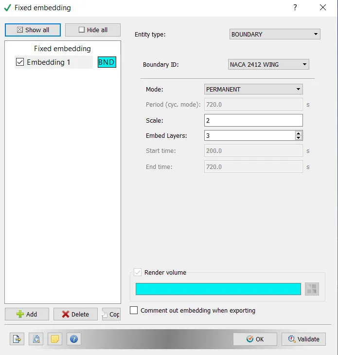
- Fixed Embedding:
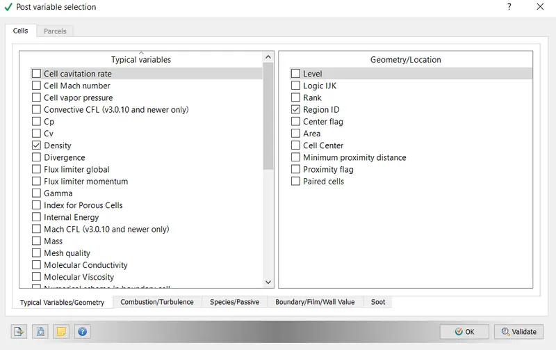
- Post Variable:
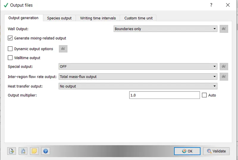
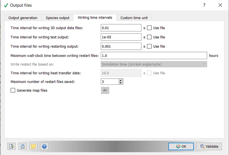
- Output Variable:
- Mesh Fixed Embedding:
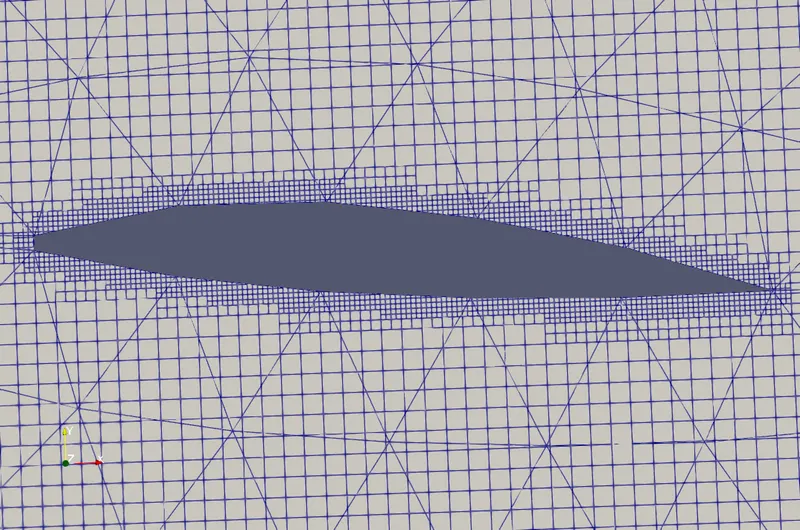
- AOA = 15 degree,

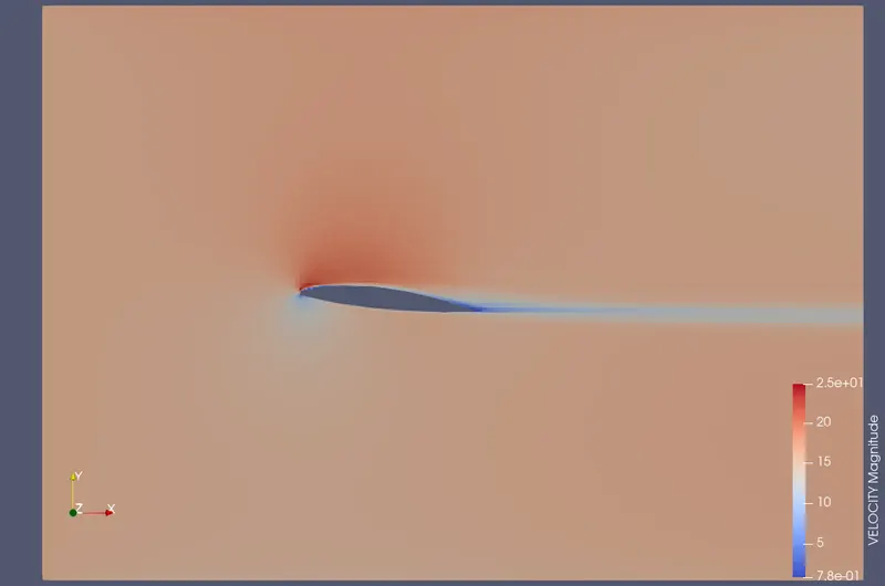
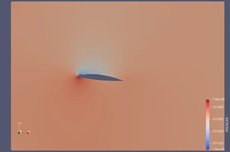
- Results images are displayed for the 15-degree angle of attack.
VELOCITY:
PRESSURE:
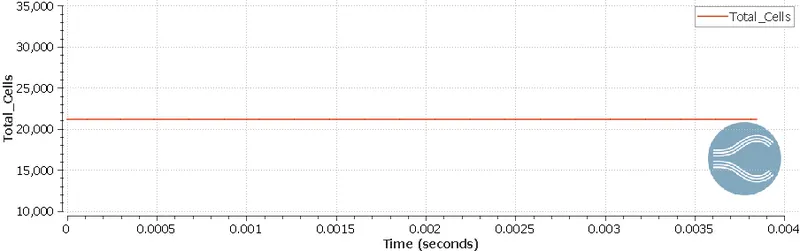
Total Cell Count:
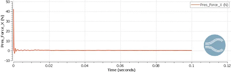
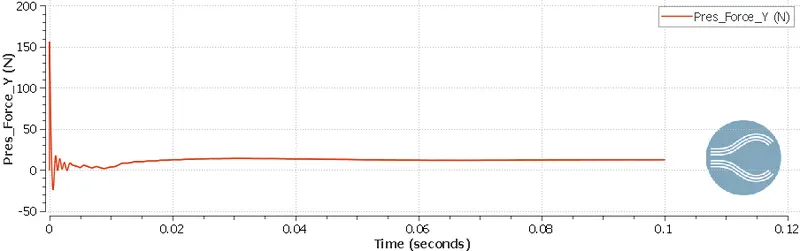
- The pressure force graphs will be shown for 2 turbulence models which are the K- epsilon & k-omega, sst models.
Pressure Force in X-Direction using k-epsilon model:
Pressure Force in Y-Direction using the k-epsilon model:
Calculating Drag Force for results obtained through the k-epsilon model:
- The dimensions of the airfoil can be determined using the image below. The bounding box dimensions will be used to calculate the dimensions.
To calculate the drag & lift coefficient, we will use the following nomenclature for the analytical method.
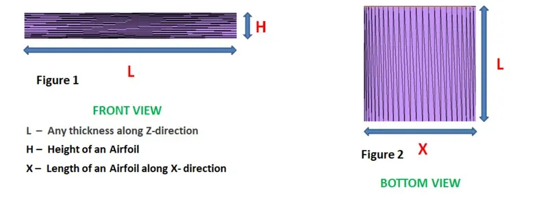
- L = 0.2m
- H = 0.024m
- X = 0.2m
The equation for the drag coefficient is as follows:
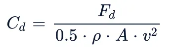
But, Converge measures the force per unit length. So, to calculate the drag force in Newton, we are multiplying it by the Length. The area of the structure can be written as Length X Height.
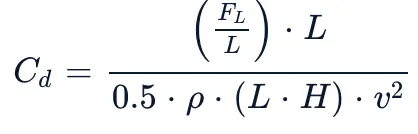
The above equation will be used to calculate the drag coefficient.
CONCLUSION:
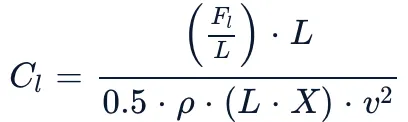
For the Lift Coefficient, a similar approach will be used. The only change is the area will be calculated as Length * X.
The following table shows the calculated drag coefficient & lift coefficient for the k-epsilon model.
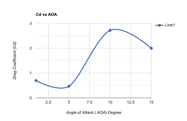
| Angle of Attack | Pressure Force in X (Fd) (N) | Drag Coefficient | Pressure Force in Y (Fl) (N) | Lift Coefficient |
| 1 | 0.59 | 0.70 | 9.3 | 1.74 |
| 5 | 0.41 | 0.47 | 20.16 | 3.81 |
| 10 | 1.90 | 2.72 | 28.57 | 4.34 |
| 15 | 1.21 | 2.00 | 29.96 | 4.69 |
- Drag Coefficient vs Angle of Attack:
- Lift Coefficient vs Angle of Attack:
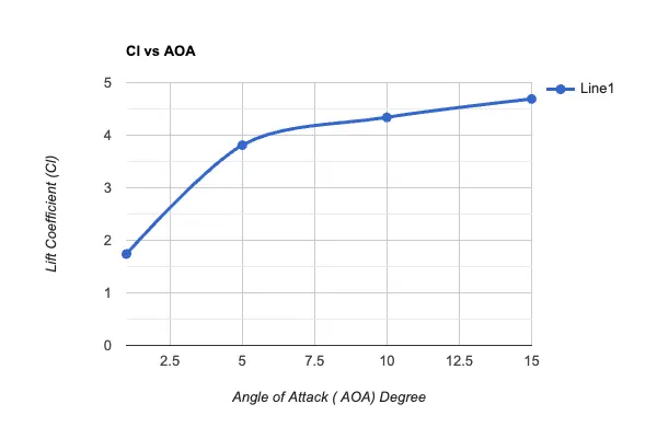
- The graphs above show that as the angle of attack increases, so does the drag coefficient and lift coefficient. The 5-degree angle decrease in drag coefficient is unusual and should not occur.