Week 9 - Mini project - Flow over an Airfoil
AIM :
Simulate flow over a 4 digit airfoil i.e NACA 2412 Airfoil.
OBJECTIVE :
We will have to calculate the following,
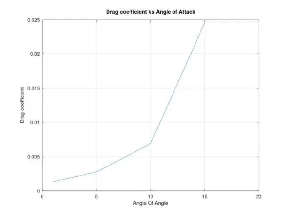
- Drag co-efficient Vs Angle of Attack
- Lift co-efficient vs Angle of Attack
- Compare the effect of turbulence models on the above two results.
- Make sure that the inlet Reynolds number is 200,000
- Make sure you do above calculations for the following angle of attacks,
- Angle of attack = 1º
- Angle of attack = 5º
- Angle of attack = 10º
- Angle of attack = 15º
Let us know the what is angle of attack
The Angle of Attack is the angle at which relative wind meets an Aerofoil. It is the angle formed by the Chord of the aerofoil and the direction of the relative wind or the vector representing the relative motion between the aircraft and the atmosphere.
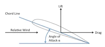
The coefficient of lift is a measure of how much lift the wing can produce and can only be changed by changing the shape of the wing or the angle of attack at which it cuts through the relative wind. We can change the shape of the wing using flaps, slats, or other similar leading and trailing edge devices. We change the angle of attack using our flight controls and, in some cases, power settings.
the pressure over and under the wing decreases as the velocity of the air increases. The pressure differential over the top and under the bottom of the wing generate the aerodynamic force that becomes lift and drag.
Procedure to creating the geometry
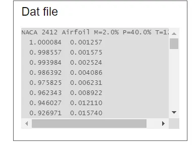
Visit the site to get .DAT file for NACA 2412 Airfoil,
This are the co ordinates for the creating the geomerty
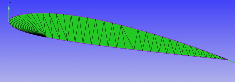
The final geometry will look like this
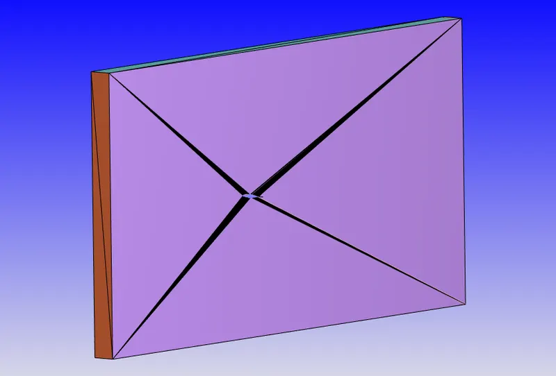
This is a setup of a virtual wind tunnel
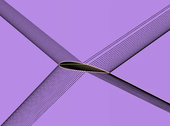
After the final dignosis
we can start the case set up
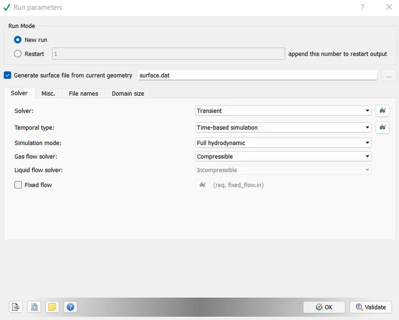
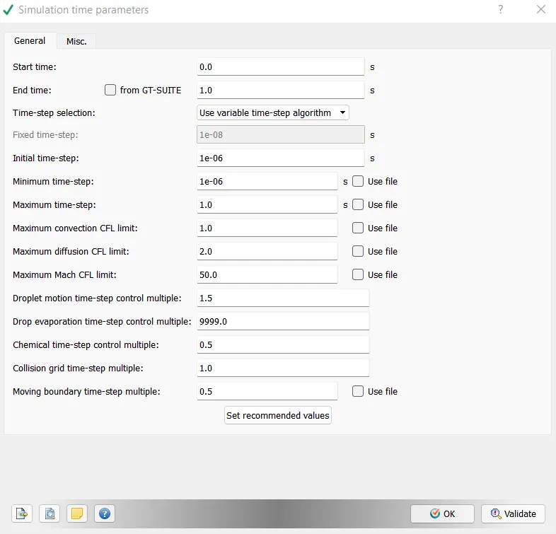
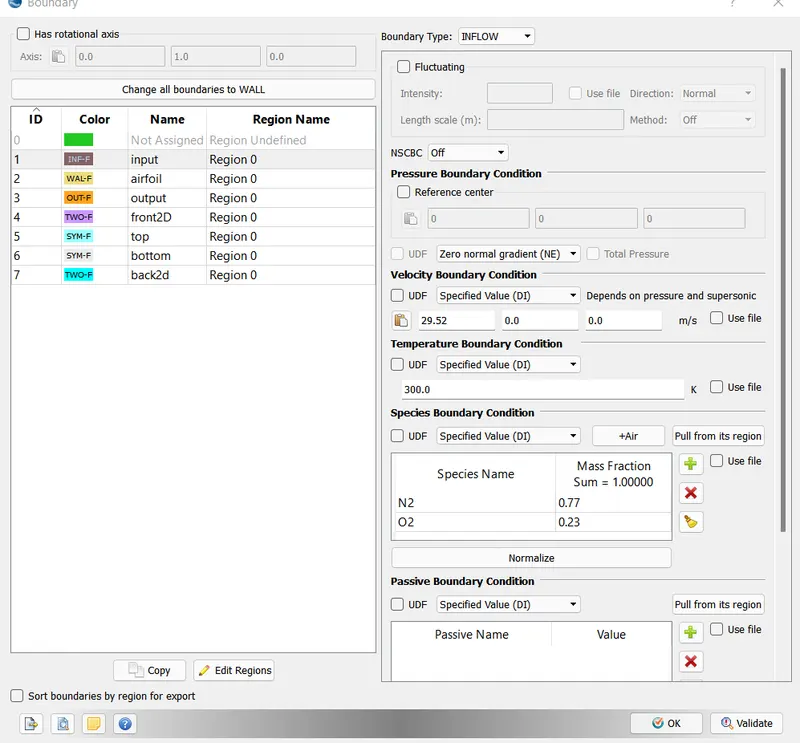
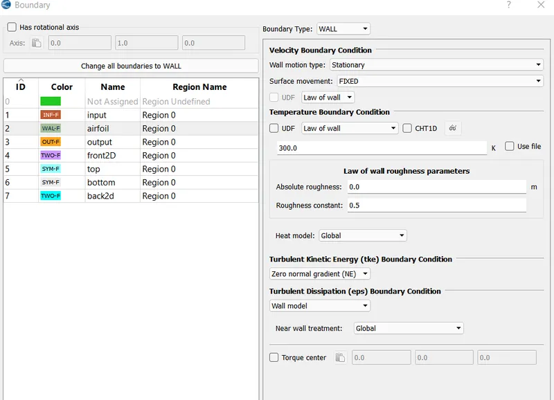
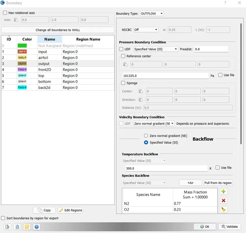
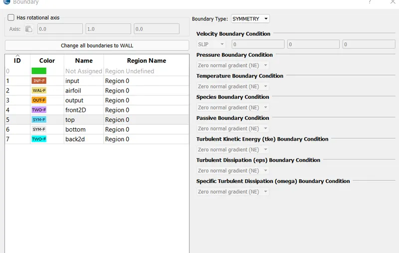
The front and back are 2D . top and bottom are symmetry
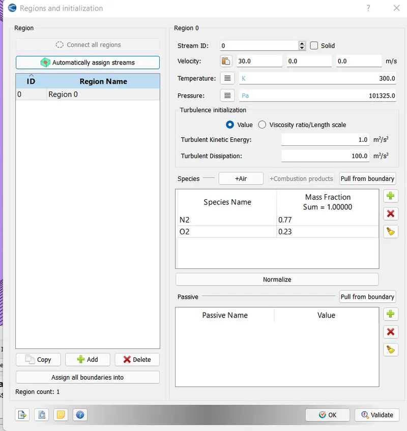
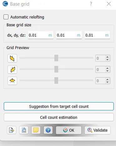
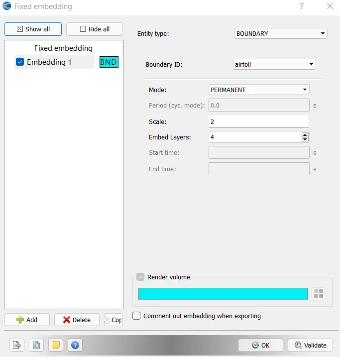
Give a calcuated outputs files and export the files to a folder and run in the CIGWIN command
After the completion Postprocess the results in converge and understand the lift and drag polts
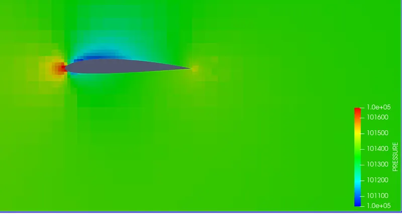
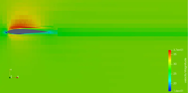
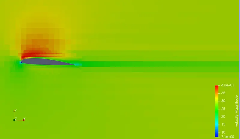
Hear are the result for 1 degree angle of attack
Mesh
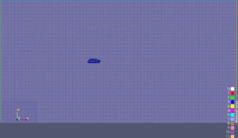
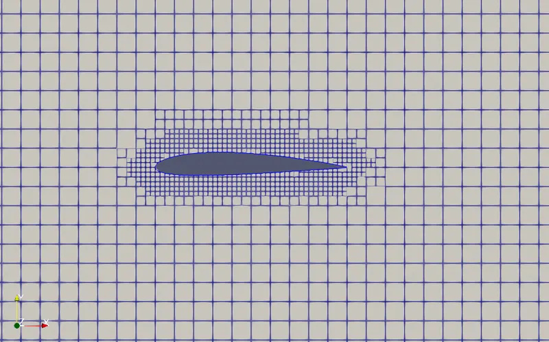
Pressure Image of Airfoil
Velocity image of Airfoil
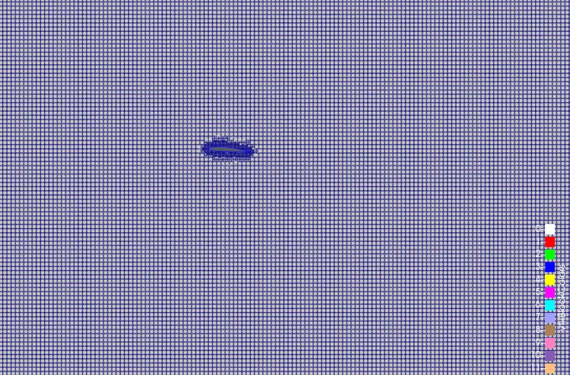
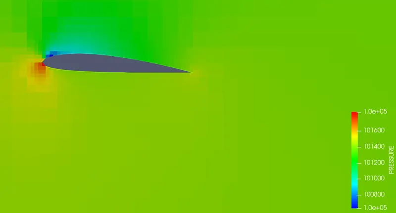
Hear are the result for 5 degree angle of attack
Mesh
Pressure Image of Airfoil
Velocity Image of Airfoil
Hear are the result for 10 degree angle of attack
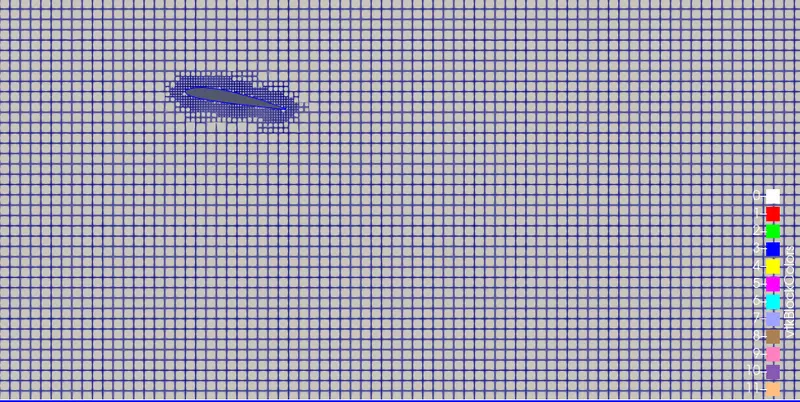
Mesh
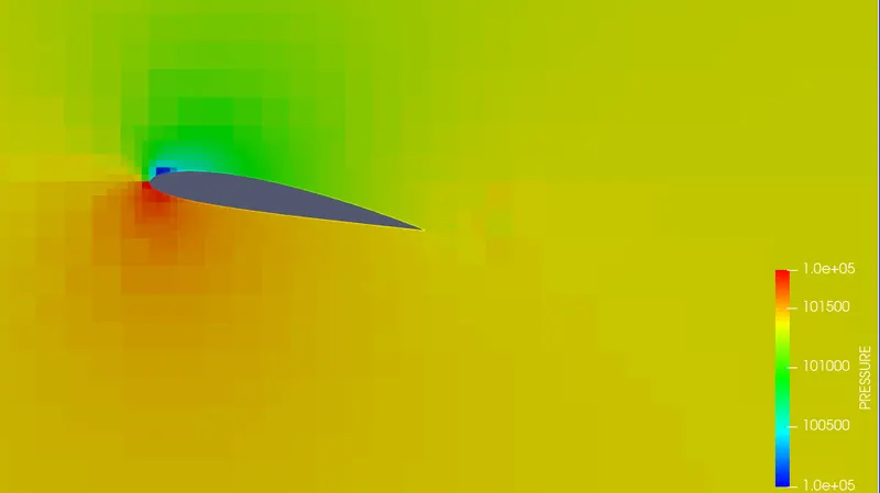
Pressure Image of Airfoil
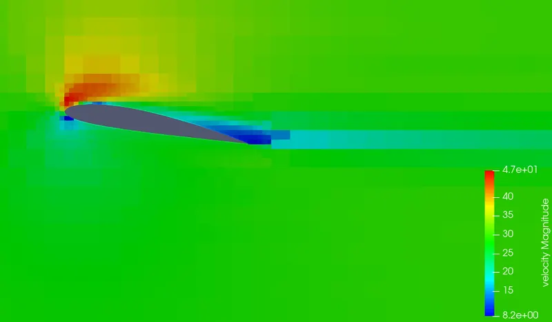
Velocity Image of Airfoil
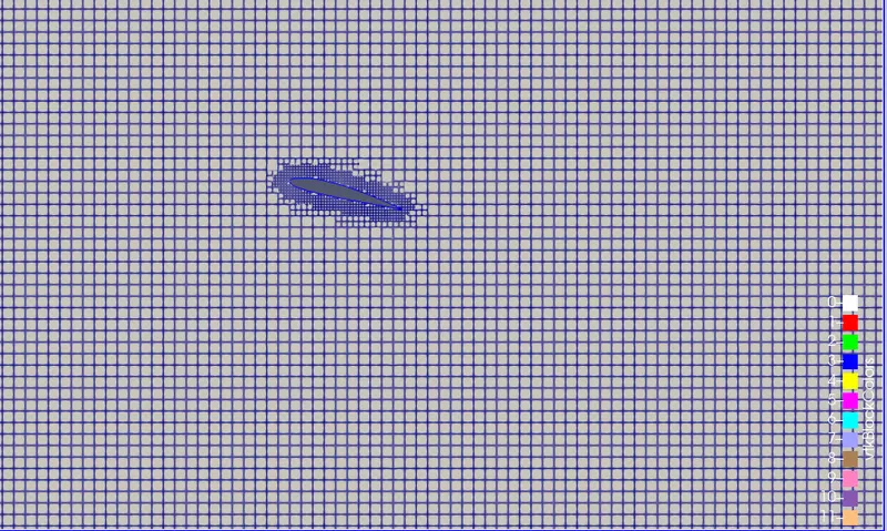
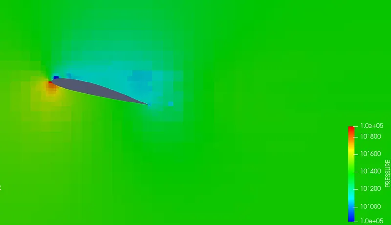
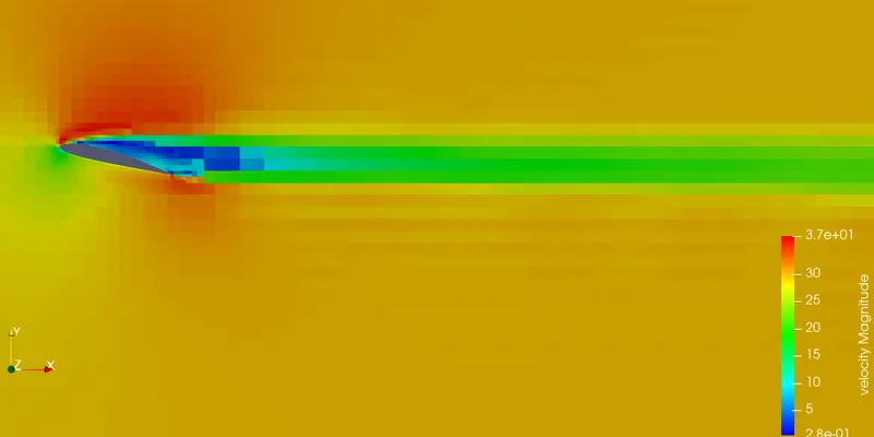
Hear are the result for 15 degree angle of attack
Mesh
Pressure Image of Airfoil
Velocity Image of Airfoil
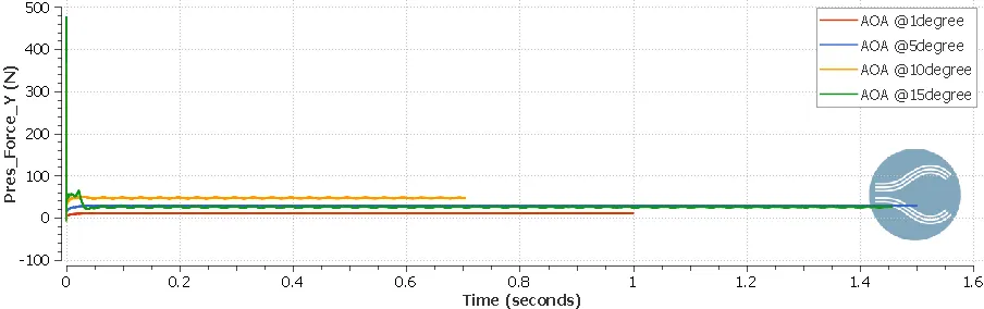
Lift Plot
AOA : Angle of Attack
Drag Plot
AOA:angle of attack
D: Degree
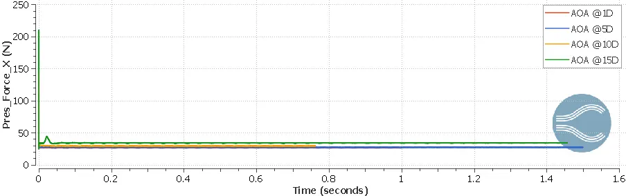
This are the plots which are simulated by the different Turbulance module
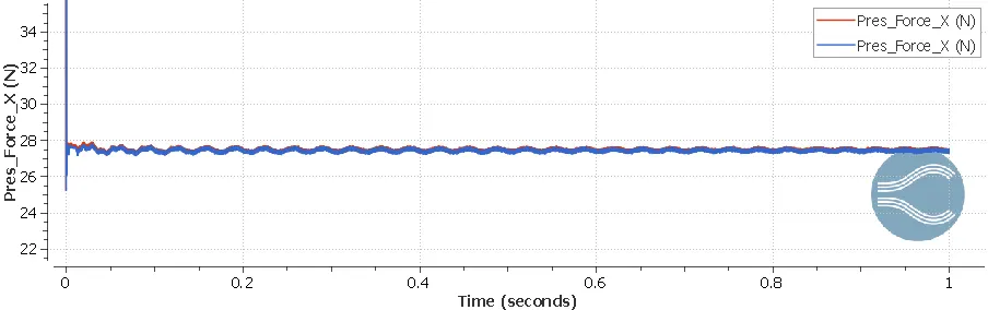
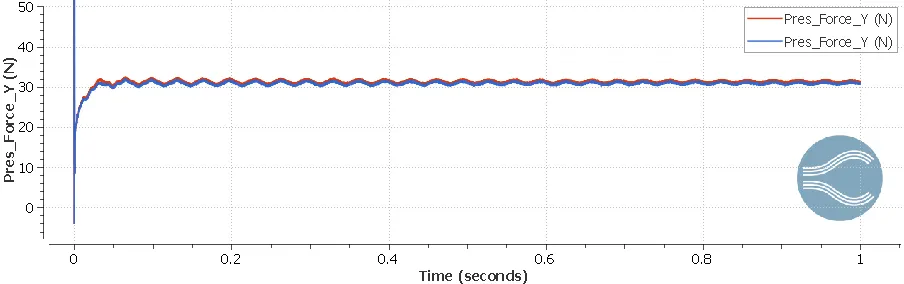
we simulated 5degree of angle of attack of k omega sst and standard k epsulon module
Drag plots
Lift polts
Drag co-efficient Vs Angle of Attack
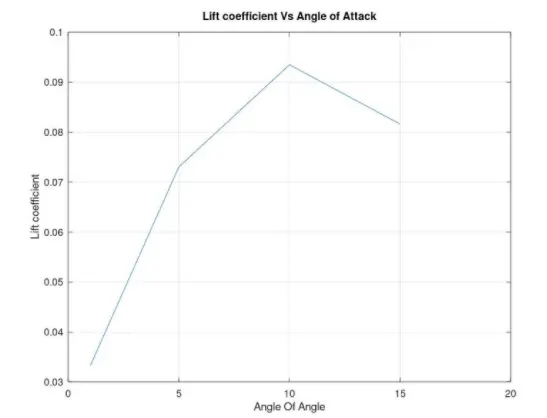
Lift co-efficient vs Angle of Attack
To calculate the Lift co-efficient & Drag co-efficient
We got a formula
cd = df/(0.5*density*area*v*v)
where cd = co-efficient of drag
df = drag force
v = velocity
Same for the Lift co-efficient cf & lf will change thats it.
by calculating all value we got a plot which we use octave to get it
CONCLUSION
From the above results, the following observations are made
The converge's steady-state solver is not suitable for this simulation.
The transient case is much more effective and the K omega SST model
calculates the physics better than RNG K epsilon.
AOA 1 Degree,AOA 5 Degree,AOA 10 Degree dos make a small differnce in lift and drag but the15 AOA has huge effect on the airfoil