Week - 9 Material Modeling from Raw Data
AIM:
To use the diagram of the true stress-strain curve of graphite iron casting and use the data to create either a MAT_024 or MAT_018 material model and then validate it.
MATERIAL MODELLING:
- Material Modelling is done in CAE industry that involves testing of new material.
- It is mainly carried out in Research and development sectors of CAE because new materials are preferred, to avoid or eliminate certain parameters and take in some new parameters that may be helpful in certain application.
- This material modelling is done using FEA tools to avoid wastage of time and effort spent into it physically.
PROCEDURE:
EXTRACTING DATA
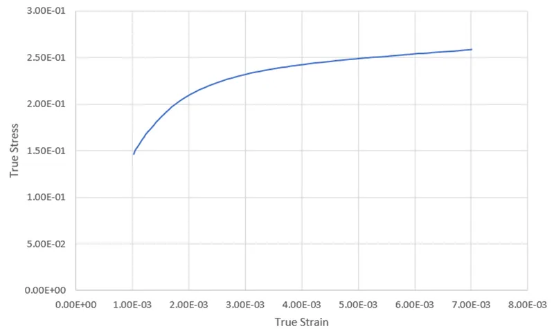
- A true stress-strain curve of graphite iron casting is given in the form of image.
- A data digitizer is used to create the data points from the curve and saved it in excel format.
- The data is then cleaned in excel.
- The true stress and strain are then changed to (kg-mm-MS) unit system.
EFFECTIVE STRESS AND EFFECTIVE PLASTIC STRAIN
Since we're modeling a elastic plastic material, we're concerned with plastic region. Therefore, effective stress and effective strain are calculated from true stress and true strain. Then we get to find the yield point from the graph
Effective stress = True stress
Effective Plastic strain = True Strain- (True Stress/E)
where, E = 20.9E+06 psi
CURVE
A loading curve and Effective stress and Effective Plastic strain curve is defined
Part
- A MAT 24 card is created here while assigning the above curve along with it.
- Create shell section with appropriate thickness.
- Assign the material and section card to the part.
BOUNDARY CONDITIONS
- A NSID is created on the left side and is constrained except for Y-direction

- A NSID is created at middle of both ends and is constrained except for X-direction
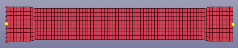
- Then a NSID is created at the right side for loading.
IMPLICIT
- Since this is a static simulation implicit method is used.
- So, under Control Implicit Keyword, Auto, General, Solver and Solution is used to define the time step and solver type.
DATABASE
- A d3plot is given to write the output of the simulation.
- ASCII: ELOUT, GLSTAT is given.
RESULT:
SIMULATION
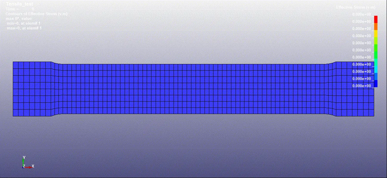
PLOTS
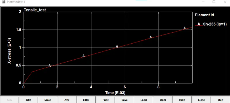
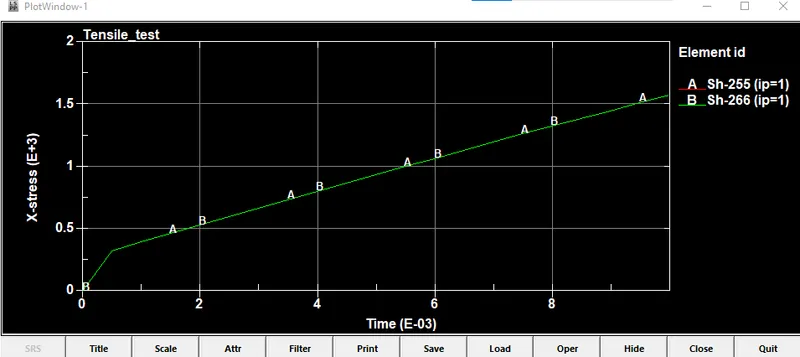
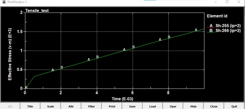
Comparing Simulation result and the given data
CONCLUSION
Therefore, the given data and simulation data almost matches with each other by performing the test on the given dog bone specimen. As a result, MAT 24 is modeled for the given material and validated.