Week 9 Machining with Planer Challenge
Explicit Dynamic Analysis of Machining with a planer:
AIM:
To study and perform explicit dynamic analysis for machining with planar operation. There will be two different analyses on the same specimen with different type of velocity and get results for Equivalent stress, Equivalent elastic strain and the total deformation in the model and grid dependency test was also performed to optimize the element size for better accuracy.
Case 1: Velocity with 20000 mm/s
Case 2: Velocity with 15000 mm/s
DYNAMIC ANALYSIS SETUP FOR MACHINING WITH PLANAR OPERATION:
I. GEOMETRY:
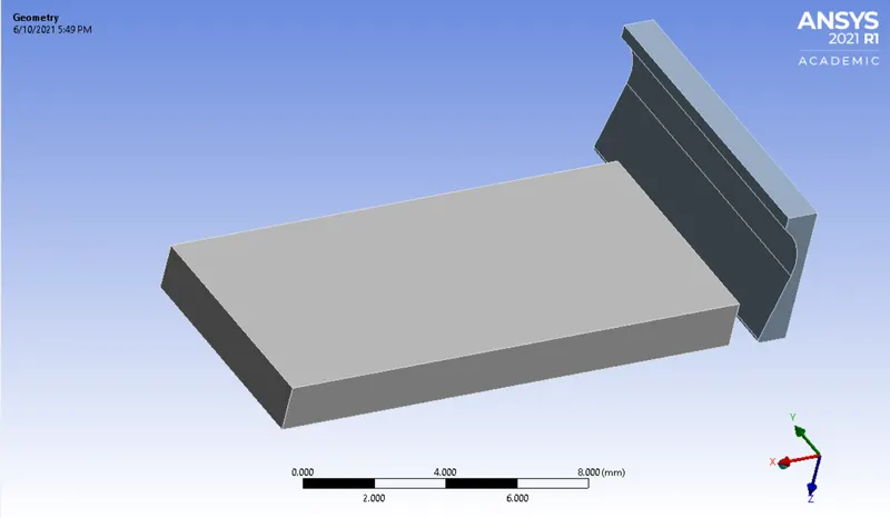
The CAD model of machining with planar operation is imported in Ansys dynamic structural environment. Then, the model is generated and checked if any abnormalities are present in the model. Generally, we have to perform two individual analysis and according to that we have to analyze the results. It is based on principle of planar machine which is the concept of relative tool-work motions.Reciprocation of the tool or job and the slow, intermittent transverse feed motions are imparted to the job or tool by the fast straight path motion cutting motion.
II. MATERIALS:
Below are the given material which is used to perform dynamic analysis of machining with planar operation. The analysis is carried out for each material individually.
Specimen: Steel 1006
The details of each material has been carried out below as shown in the image:
III. CONNECTION DETAILS:
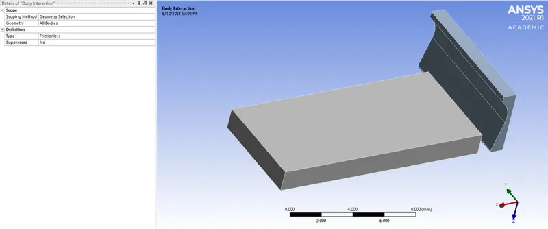
Body interactions:
In this type, all bodies are selected as its interaction part as its geometric selection part. As, its definition type is frictionless.
IV. MESH:
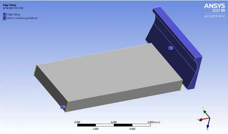
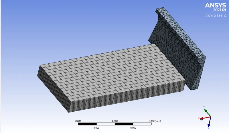
- Basically, we have preferred default mesh for whole setup.
- As, we have to do edge sizing for the critical part, hence we have selected 4 edges as critical part and given number of divisions as 10.
- Also, we have add patch conforming method to cutting tool as its geometric selection and defined its method as tetrahedrons.
- Likethat, we have generated the fine mesh which is sufficient to carrry out simulation which gives desired results.
V. ANALYSIS SETTINGS AND BOUNDARY CONDITIONS:
A. ANALYSIS SETTINGS:
For this analysis the number of steps is set to 1 with maximum number of cycles is 1e+07 and end time is 7e-4 and it is defined by time, hence initial, maximum and minimum time will be program controlled. Basically, the maximum energy error for case 1 and case 2 is 0.1 and 0.25.
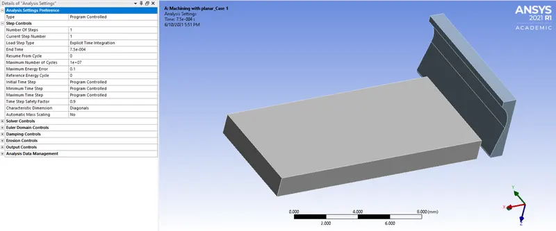
B. BOUNDARY CONDITIONS:
1. Fixed Support:
Basically, we have to fix the part so to analyze the results. Therefore, we have fixed the 1 face of workpeice section as its geometric selection and we have selected it as fixed type support.
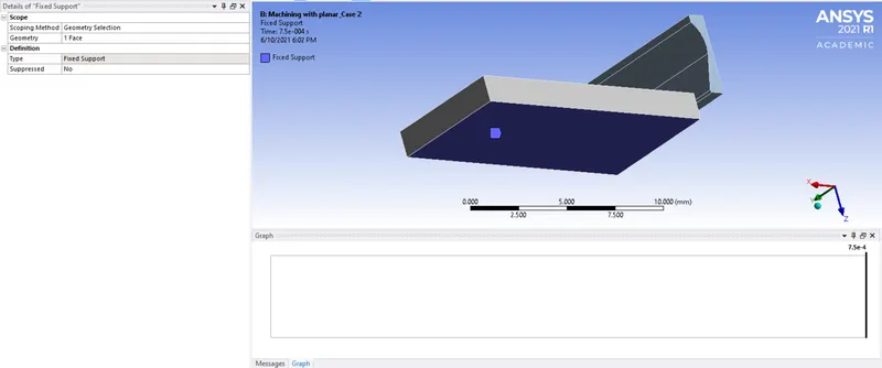
2. Velocity:
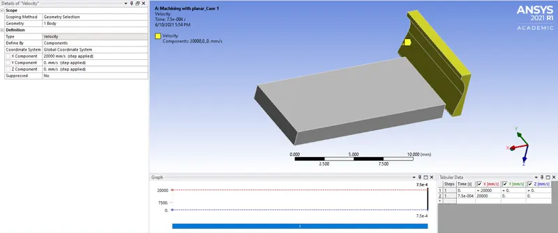
Case 1: Velocity with 20000 mm/s
As, we have to select the cutting tool as its geometric selection part. Then its type is specified by velocity and its coordinate system is defined by 'Global coordinate system'. Then, its Y and Z component gets value as constant and X component value gets linear direction displacement in tabular form.
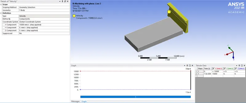
Case 2: Velocity with 15000 mm/s
As, we have to select the cutting tool as its geometric selection part. Then its type is specified by velocity and its coordinate system is defined by 'Global coordinate system'. Then, its Y and Z component gets value as constant and X component value gets linear direction displacement in tabular form.
VI. POST-PROCESSING RESULTS:
Now, we have to compare the strain, deformation and stress on the basis of given material. Then, we have to analyze the result for total deformation, equivalent stress and strain for dynamic analysis for machining with planar operation. The results are as shown below:
Case 1: Velocity with 20000 mm/s
I. Directional Deformation:
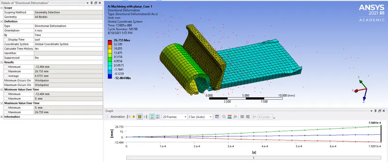
- Deformation is 26.755 mm in the X-direction.
II. Equivalent stress:
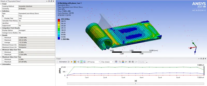
- Maximum stress is 439.34 MPa at the end.
- As per the plots and data, we can see that, once the value of stress reached upto 676.75 Mpa, then it nearby reaches it during the cutting time.
- We can see that, maximum stress is occuring at the edge of the cutting tool, from where the chip generation is occured during the cutting.
III. Equivalent elastic strain:
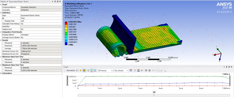
- We can see the plastic strain upto max 2.3953e-003 mm/mm due to deformation of the material.
- Due to cutting process, cut chips are generally deforms permanently, so the plastic deformation is desirable here.
IV. Tempreature generated:
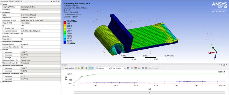
- Due to high speed cutting, we can see the tempreature is going upto maximum 367.77 °C.
Case 2: Velocity with 15000 mm/s
I. Directional Deformation:
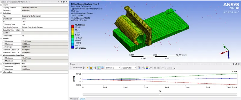
- Deformation is 19.125 mm in the X-direction.
II. Equivalent stress:
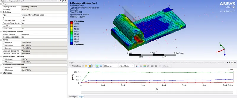
- Maximum stress is 634.19 MPa at the end.
- As per the plots and data, we can see that, once the value of stress reached upto 675.12 Mpa, then it nearby reaches it during the cutting time.
- We can see the red portion, where maximum stress is occuring at the edge of the cutting tool, chip is generating due to cutting and to resist the tool, very high stress is observed.
III. Equivalent elastic strain:
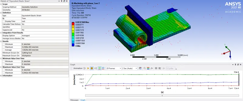
- We can see the plastic strain upto max 3.2368e-003 mm/mm due to deformation of the material.
- Due to cutting process, cut chips are generally deforms permanently, so the plastic deformation is desirable here.
IV. Tempreature generated:
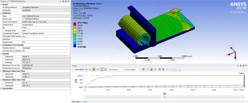
- Due to high speed cutting, we can see the tempreature is going upto maximum 364.74 °C.
VII. POST-PROCESSING RESULTS:
|
Parameters |
Case 1 |
Case 2 |
|
Maximum Directional Deformation |
26.755 mm |
19.125 mm |
|
Minimum Directional Deformation |
-12.484 mm |
-15.576 mm |
|
Maximum Equivalent elastic strain |
2.3953e-003 mm/mm |
3.2368e-003 mm/mm |
|
Minimum Equivalent elastic strain |
0 |
0 |
|
Maximum Equivalent stress |
439.34 MPa |
634.19 MPa |
|
Minimum Equivalent stress |
2.3969 MPa |
3.2868 MPa |
|
Maximum Temperature Generated |
367.77 °C |
364.74 °C |
|
Minimum Temperature Generated |
19.85 °C |
19.85 °C |
- Here from the comparision, we can see that stress in Case_2 is higher when the velocity is 15000 mm/s. When the velocity is low, material can resist more to the load and the stress can be higher.
- But the plastic strain and deformations are higher in Case_1, which is due to high velocity up to 20000 mm/s.
- Also, the temperature in Case_1 is higher, as we know that the velocity in Case_1 is 20000 mm/s, so with the speed, more amount of cutting of material will be faced by the tool in short time, so the heating will be more due to higher interaction between tool and workpeice, so the temperature will be higher in Case_1.
CONCLUSION:
- From above results, we can conclude that during the planer machining, high stresses in the chip formation zone, secondary deformation zone as well as on the machined surfaces can be generated
- Intensity of stress and behaviour of the chip formation depend on the sheer angle of the cutting tool.
- We can observe excessive increase in the tempreature during the machining process.
- When the velocity of the cutting tool is low, stress is high, which can cause the failure of cutting tool or the wearing of the tool, will be high.
- By analyzing different velocity of cutting tool, we can find the optimum velocity and can reduce the stress generation on the workpiece.
- For better machining process, optimized layer of cutting surface, shear angle of tool and the velocity are important parameters, through which we can get smooth machined surface and good chip formation.