Week 9 Machining with Planer Challenge
Machining with Planar Assignment –
Objective –
The objective of this assignment is to perform explicit dynamic analysis of the machining operation done by the planar on a workpiece
The analysis is performed on 2 different machining velocities and behaviour of each is studied under the same metallurgies.
Simulation Case 1 – Tool with a cutting Velocity of 20000 mm/s
Model and Analysis Set up
- Model Geometry
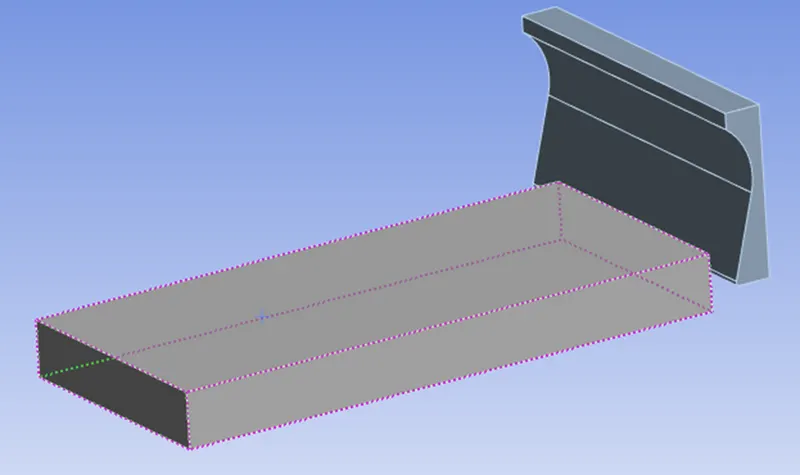
The model is created in a CAD software and imported in ANSYS, initially checked in Space claim
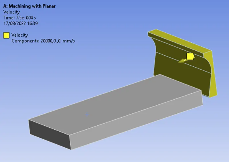
The rectangular block is the workpiece and the curved part is the tool.
See below model snapshot.
- Materials
Explicit materials are used in this analysis, materials to be Explicit Steel 1006 for the workpiece and Structural Steel for the tool.
- Contacts and Joints
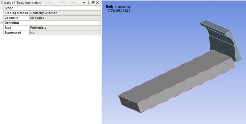
No Contacts are defined for this simulation case
Frictionless body interactions are defined
- Meshing
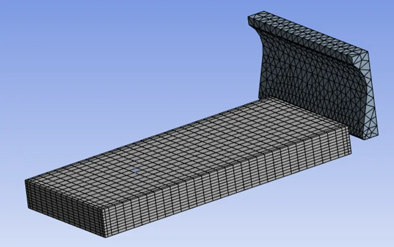
The tool is meshed with default size but the mesh method is tetrahedrons.
The workpiece is meshed in 10 divisions since it is in perfect rectangular shape.
- Analysis Settings
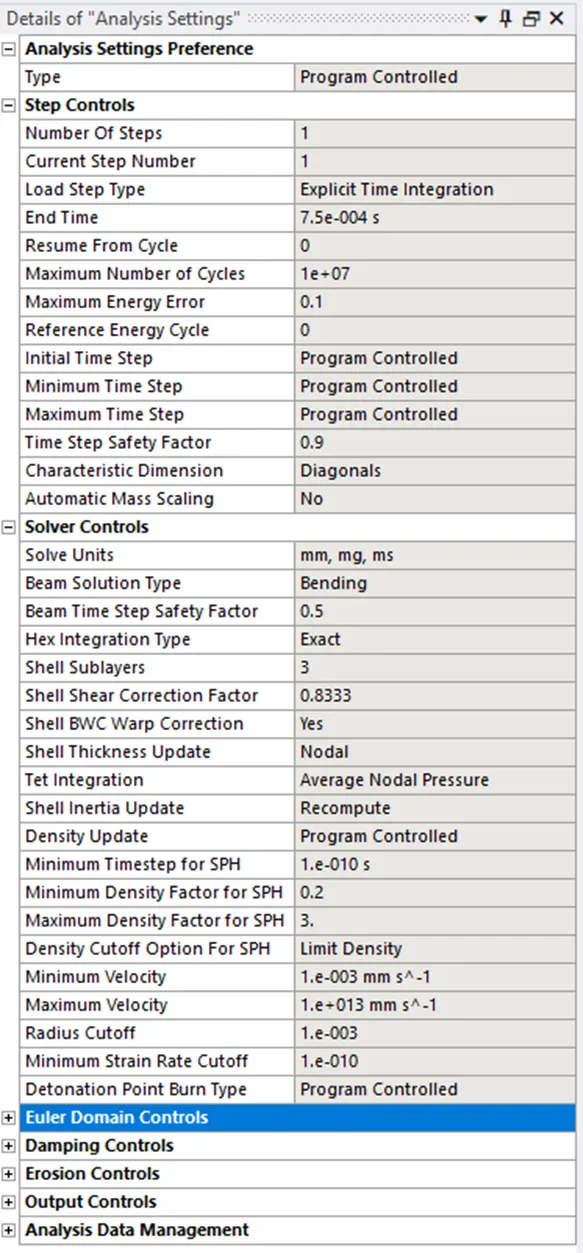
Since it’s an explicit dynamics analysis, it is performed on a very short end time step = 7.5 e-4
The other time steps are kept as program controlled as we do not know the sound wave propagation over the each elements.
Rest of the setting are kept as default.
- Loads and Supports
The tool is assigned with a velocity of 20000 mm/s along the longitudinal direction (X-direction) of the workpiece.
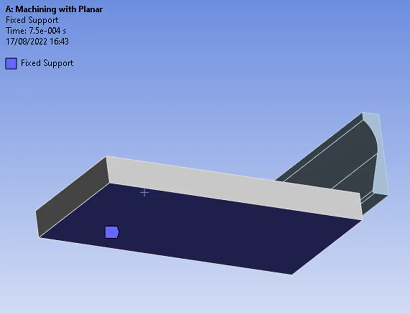
The workpiece is assigned with fixed support at the base so that equilibrium is maintained.
The model is solved for the results, and the required results are plotted as below
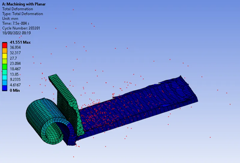
- Total Deformation
The total deformation = 41.55 mm
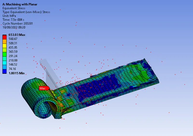
- Equivalent Stress
The maximum stress in the workpiece – 653.03 MPa
Location – on the edge where tool and workpiece stop.
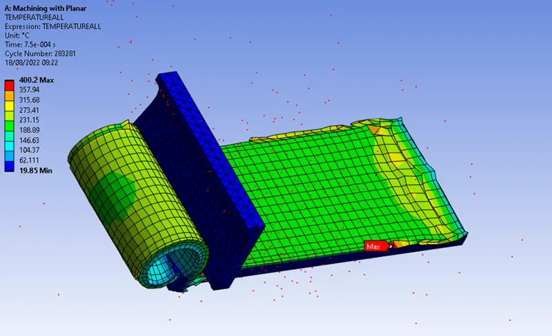
- Temperature of the Workpiece
The maximum temperature in the workpiece = 400 0C
It occurs where the tool brazes past the non-machined part of the workpiece
Simulation Case 2 – Tool with a cutting Velocity of 15000 mm/s
Model and Analysis Set up
- Model Geometry
Same as Case 1
- Materials
Same as Case 1
- Contacts and Joints
Same as Case 1
- Meshing
Same as Case 1
- Analysis Settings
Same as Case 1
- Loads and Supports
The tool is assigned with a velocity of 15000mm/s along the longitudinal direction (X-direction) of the workpiece.
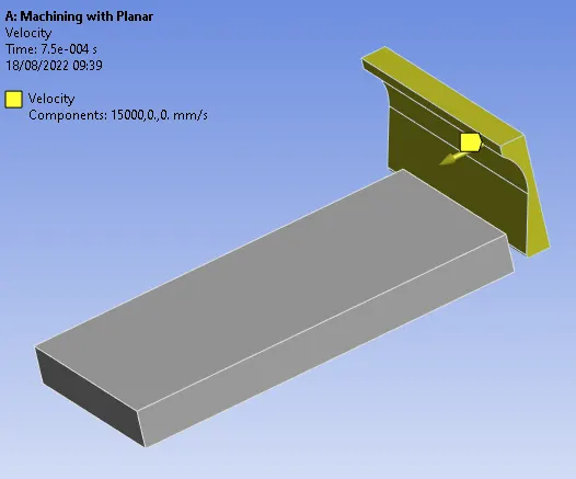
The workpiece is assigned with fixed support at the base same as Case 1 so that equilibrium is maintained.
The model is solved for the results, and the required results are plotted as below
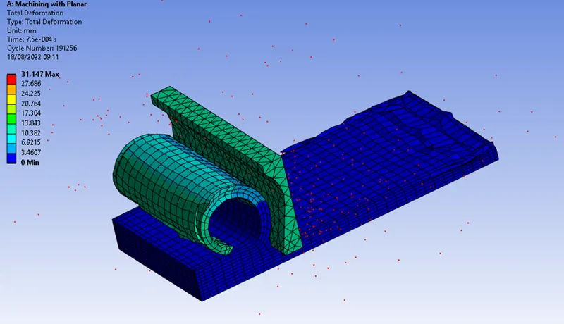
- Total Deformation
The total deformation = 31.147 mm
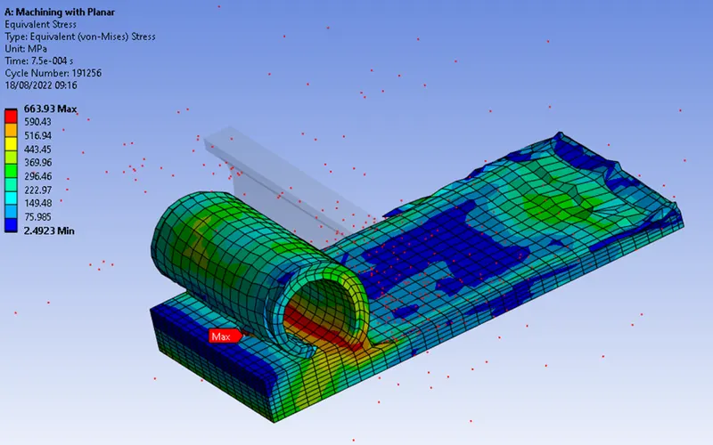
- Equivalent Stress
The maximum stress in the workpiece – 663.9 MPa
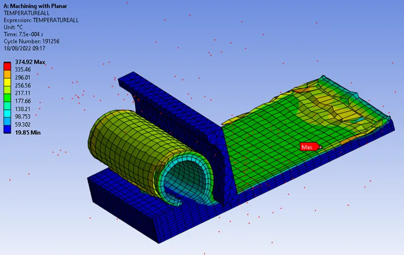
- Temperature of the Workpiece
The maximum temperature in the workpiece – 374.9 0C
- Results and Conclusion
The comparison of the results for the 2 cases are tabulated as below –
|
Design Case |
Deformation (mm) |
Maximum Stress (MPa) |
Temperature in the Workpiece 0C |
|
Case 1 – Tool with a cutting velocity of 20000 mm/s |
41.55 |
653.03 |
400 |
|
Case 2 – Tool with a cutting velocity of 15000 mm/s |
31.14 |
663.9 |
374.9 |
- The total deformation is less in Case2 than Case 1 since tool moving at 15000 m/s is not adequate to complete the full machining of the workpiece.
- Stress in the workpiece is higher in Case2 because the tool stops on the workpiece without completing the operation hence the workpiece acts as a restraint for the tool thus stressing it higher than Case1
- Higher temperature is generated on the workpiece in Case1 as the tool moves with larger velocity creating higher energy motion than Case2