Week 9 Machining with Planer Challenge
AIM: To simulate the machining with planer process in Ansys Workbench.
Objective:
To perform an explicit dynamics simulation to find out the Equivalent Stress, Total Deformation and also to insert a user defined result to calculate the temperature of the body where one will be with a cutting velocity of 20000mm/s and the other will be with a cutting velocity of 15000mm/s.
Introduction:
A planer is a type of metalworking machine tool that uses linear relative motion between the workpiece and a single point cutting tool to cut the work piece. A planer is similar to a shaper but larger and with workpiece moving, whereas in a shaper the cutting tool moves. The most common applications of planers are linear-toolpath ones, such as generating accurate flat surfaces, cutting slots (such as keyways),etc..
The working principle of the planer machine is a Quick return motion mechanism. While the workpiece moving forward the forward strokes complete and while it moving back the return stroke complete. In a forward stroke, the material is cut and in backward no material is cut.
Procedure:
- After opening Ansys Workbench, use explicit dynamics as the mode of analysis for simulation.
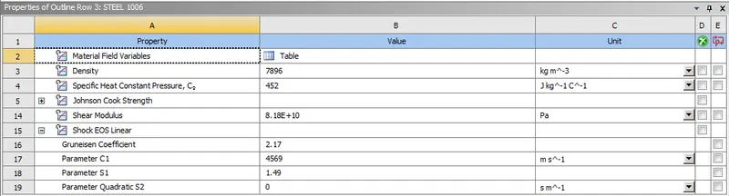
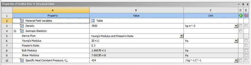
- Now, add steel 1006 explicit material for workpiece and structural steel for the cutting tool from the engineering data tab in project menu.
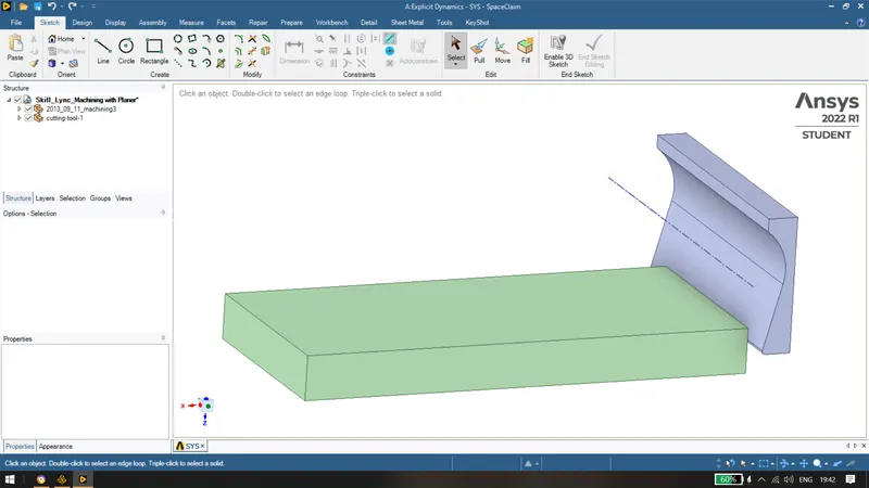
- Import the model provided and check the geometry in the Ansys Spaceclaim for any abnormalities.
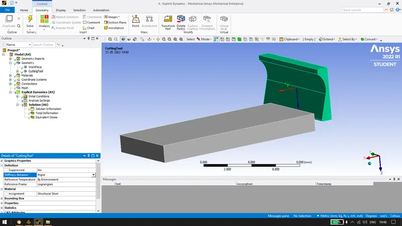
- Now in Ansys mechanical, rename the two components as workpiece and cutting tool. Assign the materials as mentioned above and change the stiffness of the cutting tool to be rigid.
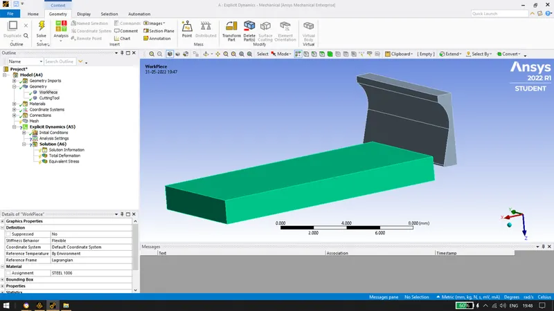
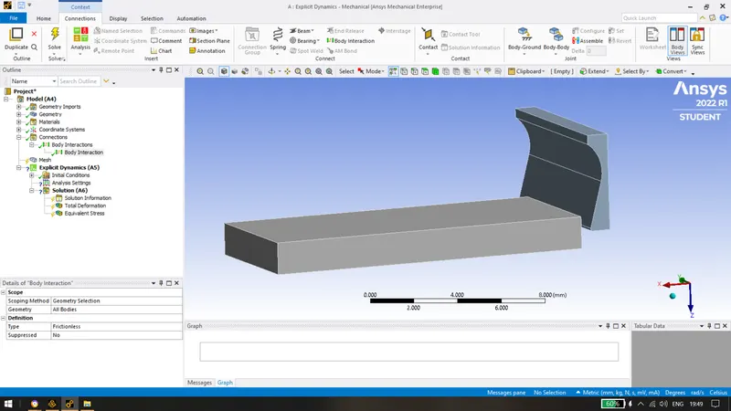
- Now, delete the default contacts created by ansys because no contacts are required for the simulation.
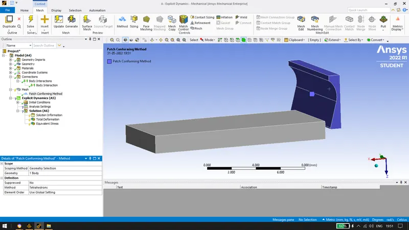
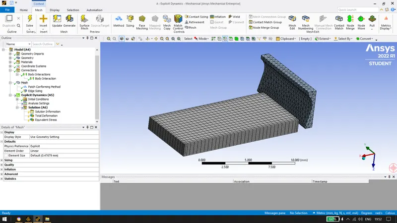
- Mesh the components with default element size, inserting sizing mesh at the 4 edges of the workpiece and set it to by division to 10 and also convert the cutting tool into tetrahedron by using method.
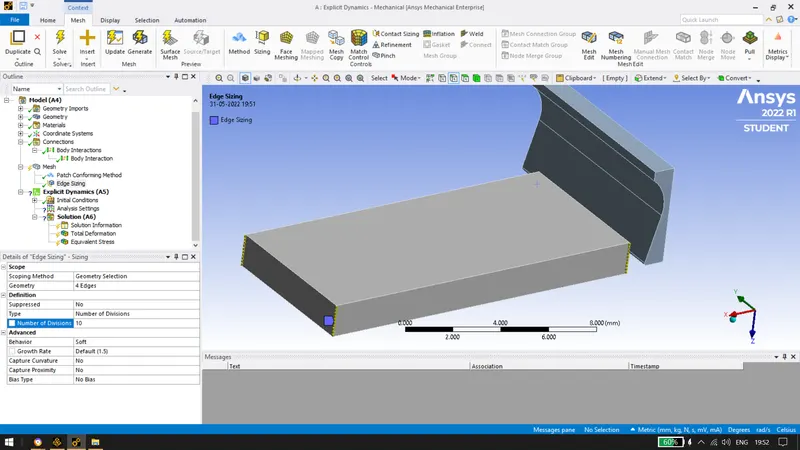
Final Mesh obtained is:
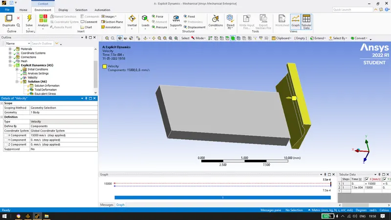
- Apply a velocity of 15000mm/s to the cutting tool in x direction and restrict the y & z directions.
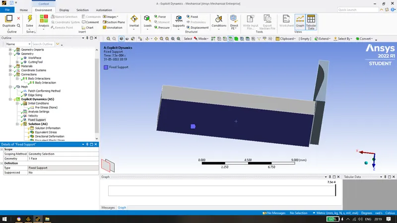
- Adding fixed support to the base of the workpiece so that there is no movement of the workpiece while machining.
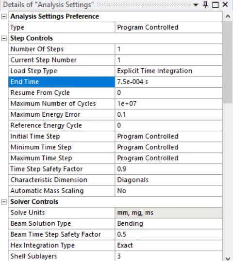
- Following analysis settings have been used for the simulation with an end time of 0.00075 seconds.
- Insert directional deformation, equivalent plastic strain and equivalent stress.
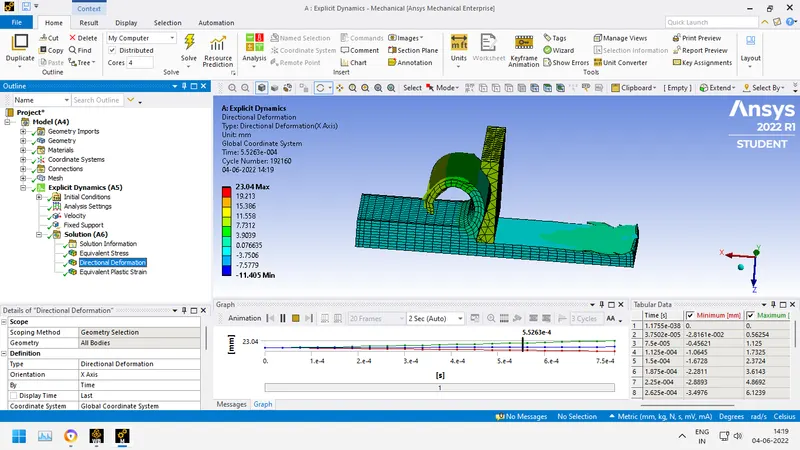
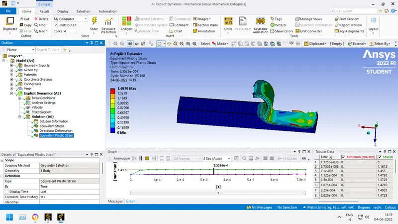
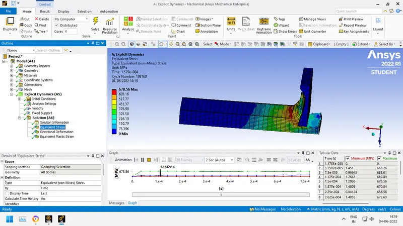
- Finally following solutions have been obtained after running the simulation for the machining process.
Directional deformation of 23.04 mm was observed with max equivalent plastic strain as 1.4939 and Max Equivalent stress of 678.56 MPa was observed.
- Follow the same procedure mentioned above for the next case i.e. with a cuutting velocity of 20000mm/s.
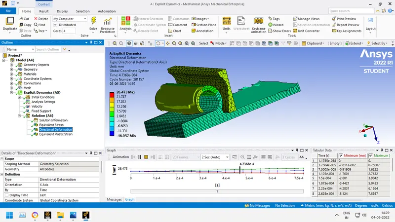
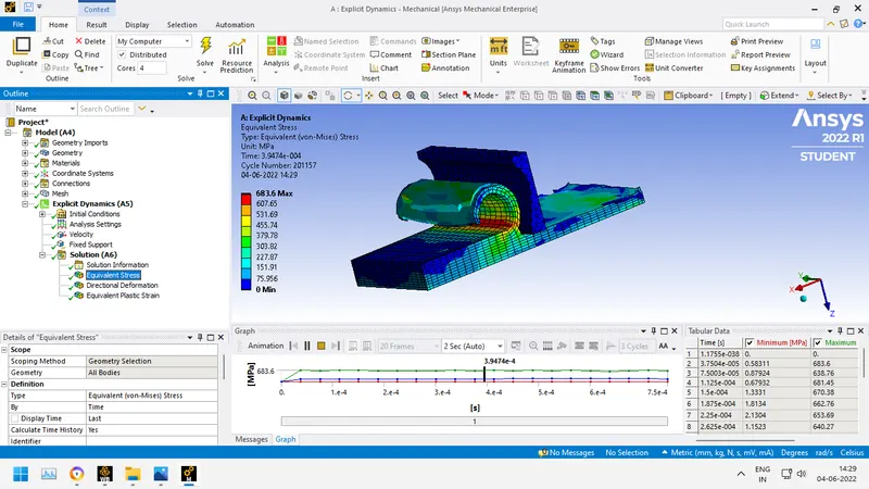
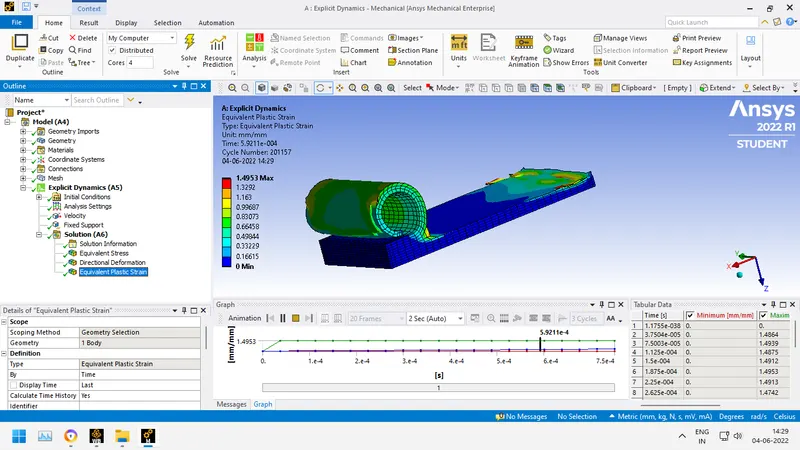
Directional deformation of 26.473 mm was observed with max equivalent plastic strain as 1.4953 and Max Equivalent stress of 683.6 MPa was observed.
CONCLUSION:

As the velocity of the tool increases while machining, the max stress induced on the workpiece increases and the directional deformation also increases. The max equivalent plastic strain is almost the same in both the cases. The temperature also increases with increase in cutting tool velocity.