Week 1 Challenge 2
Aim: To compare the performance of three different types of beams under a bending load, i.e., Rectangular Beam, I Beam and C Beam.
Introduction:
Beams are horizontal structural elements that withstand vertical loads, shear forces, and bending moments. They transfer loads that imposed along their length to their endpoints such as walls, columns, foundations, etc.
CLASSIFICATION OF BEAMS:
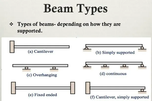
Generally, beams are classified by the shape of their cross-section, by their length, and by their equilibrium conditions and also according to their support conditions.
- SIMPLY SUPPORTED BEAMS:
A simply supported beam is supported at both ends. These beams are primarily used in general construction. Supported freely to rotate at the two ends on walls or columns. Have no moment of resistance at support.
- CONTINUOUS BEAMS
A beam that has more than two supports this kind of beam is called a continuous beam. Two or more two supports are used between these beams, and these beams are similar to the simply supported beams. Supported on two or more vertical supports. It is considered a more economical beam as compared to others. The beam over which both sides have an overhanging is called a double overhanging beam.
- FIXED BEAMS:
A beam that is fixed at both ends is called a fixed beam. Fixed beams are not allowed the vertical movement or rotation of the beam. In this beam, no bending moment will produce. Fixed beams are only under the shear force and are generally used in the trusses and like other structures. Both ends of the beam are rigidly fixed with supports.
- CANTILEVER BEAMS:
A fixed beam at one end and accessible on the other end is called an overhanging beam. These beams carry loads of both shear stress and bending moment. These beams are generally used in the bridge trusses and other structural members. It’s one end fixed in-wall or column, and the other side is free. In the cantilever, the tension zone is located at the top and compression at the bottom.
- OVERHANGING BEAMS:
A beam supported by two points but on the third point is hanging or not help is called an overhanging beam. It is a combination of the cantilever and the simply supported beam. Its ends extend beyond the columns or walls. The overhanging portion is unsupported or may locate both sides of the beam.
Procedure:
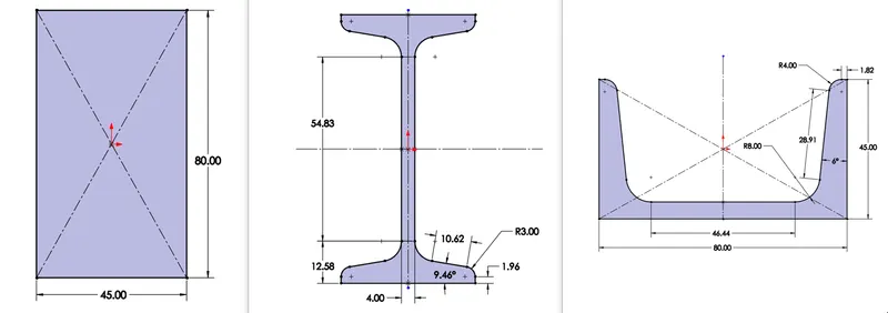
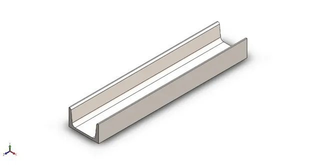
- According to the given challenge above we will be creating the sketches of the 3 beams as follows. We create the sketches of all three beams in different files in the right plane.
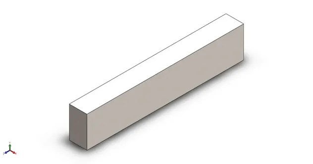
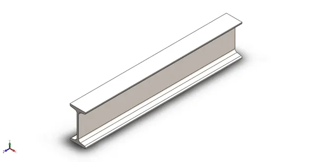
After extruding them by 400mm we obtain the following.
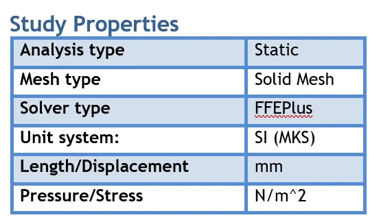
- We then create a new simulation study for all three beams as static linear study with study properties as follows:
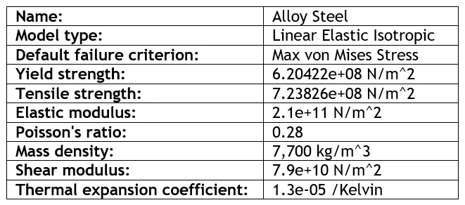
- We will apply the material to all three beams i.e., Alloy Steel and note down their properties.
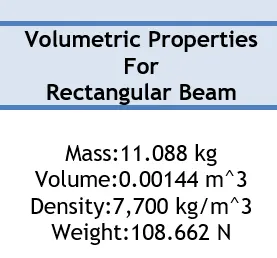
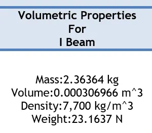
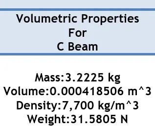
After applying the alloy steel to the beams we have obtained the following volumetric properties as follows:
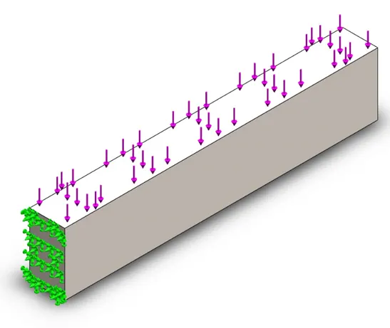
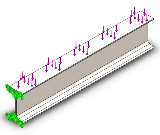
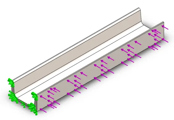
- We will fix a face (Green Region) and apply the load of 1500N (Purple Region) on the smallest face of every beam as shown in the above question.
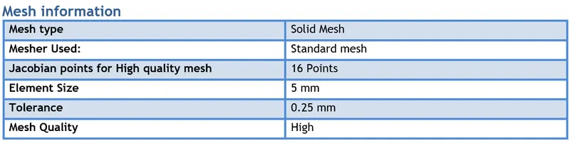
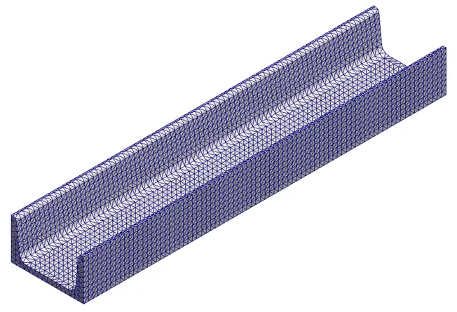
- We will be meshing the part with the following parameters for all three beams.
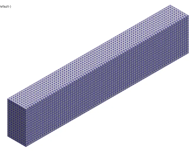
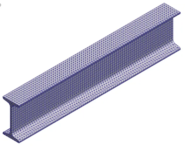
After meshing, following results obtained for all three beams:
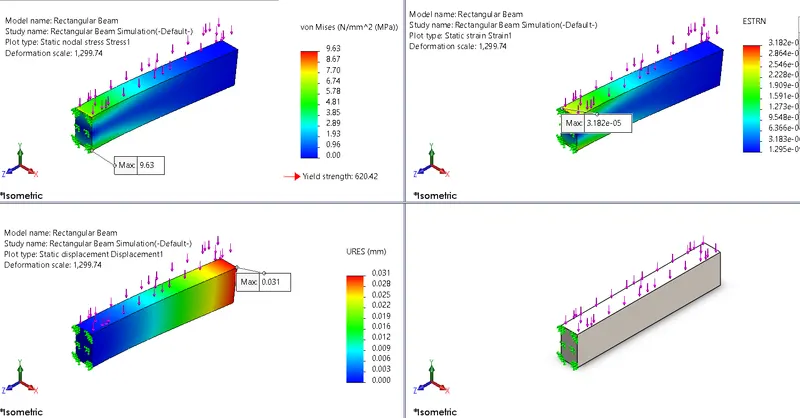
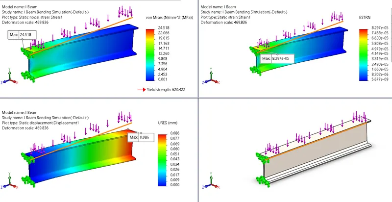
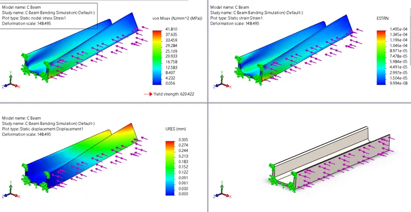
- We now run the study for our analysis. And the following results have been obtained for all three beams with stress, displacement and strain plots. Comparing them.
A) Rectangular Beam:
B) I Beam:
C) C Beam:
We now will study and conclude the above results.
Conclusion:
Now comparing the results of their performance based on stresses developed in the beams, their mass, their displacement, etc.

From the above table, we can see that
1. The maximum stress and maximum displacement has occured in C Beam as compared to Rectangular and I beam. It is also developing twisting i.e. torsional stresses as seen above. Hence, C beams cannot be used from the above.
2. The least stress and least displacement has occured in Rectangular Beam as compared to I Beam and C Beam. So, it seems to be best in terms of performance but the mass of the rectangular beam is 4.69times the mass of I beam and 3.44times the mass of C beam which in turn increases the cost of the beam. So, is is not economical.
3. The beam with the lowest mass is the I Beam which means its good for its cost. Also the maximum stress developed is 39% less than the C beam. Due to the following reasons I beam is preffered.
Also, an I-section beam is preferred because it can resist a larger moment than other cross-sections while being at same stress level.
M/I = σ/y = E/R
Where, M= bending moment,
I=Moment of inertia of the area of cross-section,
σ=Bending stress,
y=distance of extreme fibre from the neutral axis,
E=Young’s modulus,
R=radius of curvature.
As we can see M ( bending moment resisted or MOR-Moment of resistance) is directly proportional to I(moment of inertia) and an I-section has the largest moment of inertia among all the shapes of cross-section used as beams.
Animation of Stresses: https://youtu.be/IqWFn7vtQDI
References:
- https://civiconcepts.com/blog/types-of-beam
- Wikipedia
- SOM Book - RK Bansal