Week 9-Creation of 1D Connectors Challenge
AIM
To mesh the given geometry by achieving the given quality criteria and to deploy necessary connections as given.
GIVEN DATA
Here the given data are,
- Cad model.
- Quality criteria.
- Connection details.
CAD MODEL - Midsurface:
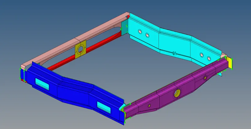
Figure 1. CAD Model
QUALITY CRITERIA:
Target Element size - 5 Units
|
S.N |
Quality Criteria |
Value |
|
1 |
Aspect Ratio |
5 |
|
2 |
Skewness |
45 |
|
3 |
Warping |
15 |
|
4 |
Taper |
0.5 |
|
5 |
Min. Length |
2 Units |
|
6 |
Max. Length |
8 Units |
|
7 |
Min angle Quad |
45 |
|
8 |
Max angle Quad |
135 |
|
9 |
Min angle Tria |
30 |
|
10 |
Max angle Tria |
110 |
|
10 |
Tria % |
15 |
Table 1. Quality Criteria
CONNECTION DETAILS:
Create connector and Attach the various parts of the given model
1. Right_Rail_2 & Front_truss_1:- Seam-Quad(angled+capped+L)
2. Left_Rail_2 & Front_truss_1:- Quad elements
3. Front_truss_2, Front_truss_1 & Right_Rail_1:- Spot weld with 2 Layers and 5 mm Diameter
4. Front_truss_2, Front_truss_1 & Left_Rail_1:- Hexa (Adhesive)
5. Rear_truss_2 & Right_Rail_2:- Bolt Connector
6. Rear_truss_2 & Left_Rail_2:- Bolt Connector
7. Right_Rail_1 & Right_Rail_2:- Spot-weld with Rigid Elements
8. Left_Rail_1 & Left_Rail_2:- Spot-weld with Spring Elements
9. Rest all the component left Join them with suitable connectors
THEORY:
CONNECTION
- Connections are nothing but representation of bolts, welds, rigid body, etc. in a FE model.
- As by its name those connector elements are used for connecting two parts.
- Here I have deployed various necessary connections.
- In this FE model, I have used BOLT connection, WELD connections, etc. as per the given cad data also assumed the welded area & deployed weld connections as the seam weld raw data has not given in this model.
- Types of connections used here are,
- Bolt connection.
- Weld connection.
- Seam weld
- Spot weld
- ADHESSIVE Connections
- RBE2 elements (Manual representation for bolt or rigid body elements)
- RBE3 elemnets (Manual representation for bolt or rigid body elements)
In Hypermesh the realization of connectors can be identified by colours,
- Red - Error in realization of connections
- Yellow - Unrealized Connections
- Green - Realized connections
MESHING:
Meshing has been performed for the given assemblies as per the quality criteria.
Connectors created and attached the various parts of the given model as by given connection data,
1. Right_Rail_2 & Front_truss_1:- Seam-Quad(angled+capped+L):
- Go to --->1D ---> Connectors ---> Seam ---> Type = Seam-Quad(angled+capped+L).
- Seam tab is attached below,

Figure 2. Seam Tab
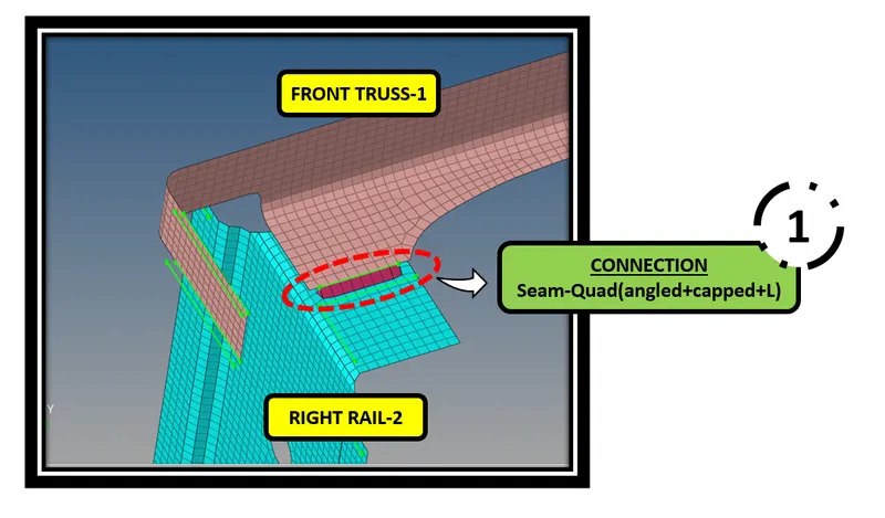
Figure 3. Seam Quad (angled+capped+L) - CONNECTIONS
2. Left_Rail_2 & Front_truss_1:- Quad elements
- Go to --->1D ---> Connectors ---> Seam ---> Type = Quad
- Seam tab is attached below,

Figure 4. Seam Tab
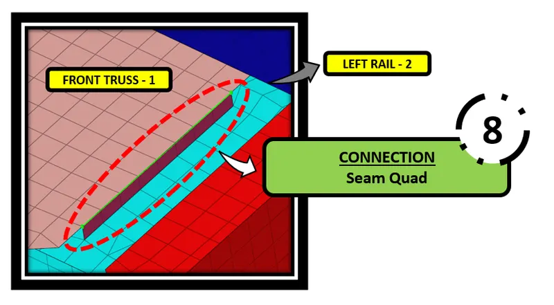
Figure 5. Seam Quad - CONNECTIONS
3. Front_truss_2, Front_truss_1 & Right_Rail_1:- Spot weld with 2 Layers and 5 mm Diameter:
- Go to --->1D ---> Connectors ---> Spot ---> Type = weld
- Spot tab is attached below,

Figure 6. Spot Tab
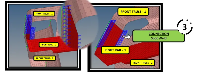
Figure 7. Spot Weld - CONNECTIONS
4. Front_truss_2, Front_truss_1 & Left_Rail_1:- Hexa (Adhesive):
- Go to --->1D ---> Connectors ---> Seam ---> Type = Hexa(adhesive)
- Adhesive tab is attached below,

Figure 8. Seam Tab
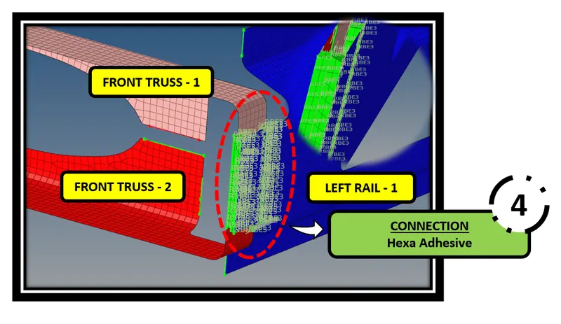
Figure 9. Hexa Adhesive - CONNECTIONS
5. Rear_truss_2 & Right_Rail_2:- Bolt Connector:
- Go to --->1D ---> Connectors ---> Bolt ---> ( Create hole, if none)
- When there is a no hole in the FE Model, The create hole, if none option is used
- Bolt tab is attached below,

Figure 10. Bolt Tab
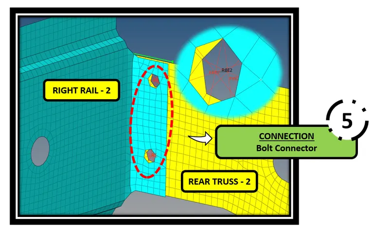
Figure 11. Bolt - Connection
6. Rear_truss_2 & Left_Rail_2:- Bolt Connector:
- Go to --->1D ---> Connectors ---> Bolt ---> ( Create hole, if none)
- When there is a no hole in the FE Model, The create hole, if none option is used
- Bolt tab is attached below,
Figure 12. Bolt Tab
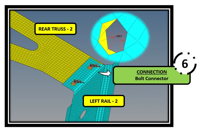
Figure 13. Bolt - Connection
7. Right_Rail_1 & Right_Rail_2:- Spot-weld with Rigid Elements:
- Go to --->1D ---> Connectors ---> Spot ---> TYPE = Rigid
- Spot weld with rigid element tab is attached below,

Figure 14. Spot Tab
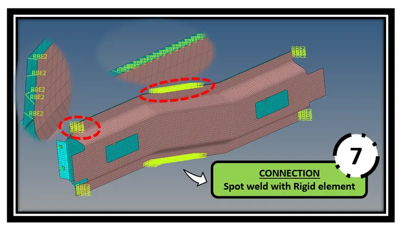
Figure 15. Spot Weld with Rigid elements - CONNECTION
8. Left_Rail_1 & Left_Rail_2:- Spot-weld with Spring Elements:
- Go to --->1D ---> Connectors ---> Spot ---> TYPE = Spring
- Spot weld with rigid element tab is attached below,

Figure 16. Spot Tab
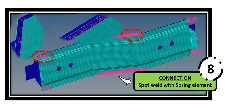
Figure 17. Spot Weld with Spring elements - CONNECTION
9. Rest all the component left Join them with suitable connectors:
- Suitable connectors has been deployed in necesaary areas as shown in the below figure.
- Seam Hexa Adhesive is deployed by using Seam weld option.
- RBE2 is deployed by using Rigid option. Go to ---> Rigids --> Element = RBE2. Here I have arrested all DOF.
- CFAST is deployed by using Rods option. Go to --> Rods ---> Element type = CFAST
- PENTA (MIG) is deployed by using Seam option, Type = Penta (Mig)

Figure 18. Rigid tab

Figure 19. Rod tab
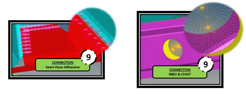
Figure 20. Seam Hexa adhesive, RBE2 & CFAST - CONNECTION
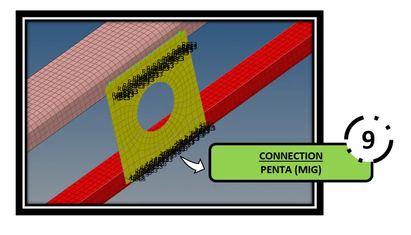
Figure 21. Penta (MIG) - CONNECTION
CONCLUSION:
The mesh has been performed by meeting the given quality criteria and also the necessary connections has been deployed successfully.
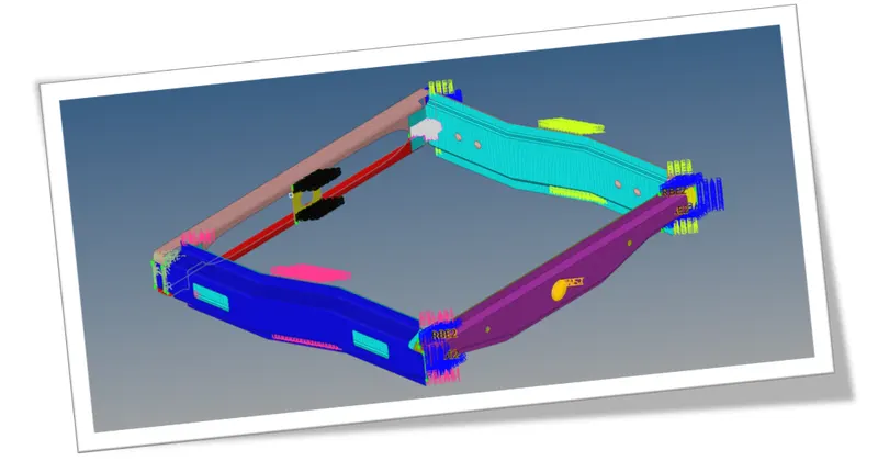
Figure 22. CONNECTIONS
LEARNING OUTCOMES
At the end of this challenge, I can able to deploy necessary connections for automotive components.