Week 9-Creation of 1D Connectors Challenge
Challenge- 9
Objective: Following the mentioned quality criteria and creating a connector at respective positions for the given frame assembly
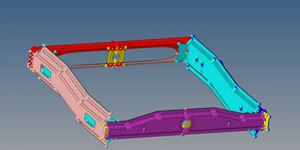
CAD Model:
Procedure:
- From the give assembly model we need to connect the components with appropriate connector among wide range of weld types and adhesives, bolt connectors, spot and seam welds.
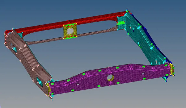
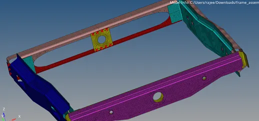
- And then we mesh the component individually to get mesh flow by taking washers at holes.
- Now we check for the elements quality for min length 2mm and max length of 8mm. we can check the elements in Check elems from Tool menu. We can set the quality parameters and check the number of elements failing for the both parameters and the we can try to remesh those failed elements or we have to rectlify the falied elements using Quality index in 2d menu. Here we can check the failed elements and can smooth the mesh and remove failed mesh elements.
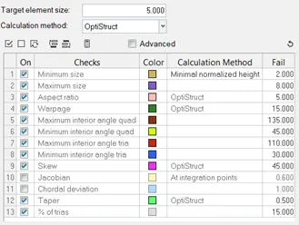
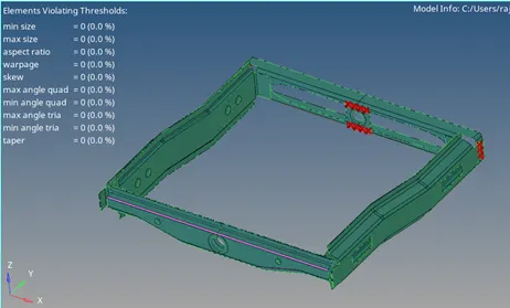
- Now as mentined we create the cnnectors one by one
- Right_Rail_2 & Front_truss_1: Seam-Quad(angled+capped+L)
Here we go to panel menu 2d connectors --> seam --> select node path and spacing as 5mm and select two components, tolerence as 5mm and type: Seam-Quad(angled+capped+L) , weld angle as 45 --> create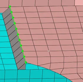
- Left_Rail_2 & Front_truss_1:- Quad elements
Here we go to panel menu 2d--> connectors --> seam --> select node path, spacing as 5mm and select two components, tolerence as 5mm and type: Quad --> create.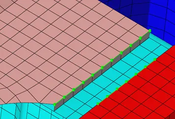
- Front_truss_2, Front_truss_1 & Right_Rail_1:- Spot weldwith 2 Layers and 5 mm Diameter
Here we go to panel menu 2d--> connectors --> spot --> select node path and number of layers as 2 and select two components, tolerence as 5mm and type: weld and diameter as 5mm --> create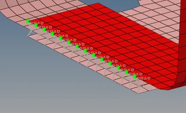
- Front_truss_2, Front_truss_1 & Left_Rail_1:-Hexa (Adhesive)
Here we go to panel menu 2d--> connectors --> seam --> select node path and spacing as 5mm and select two components, tolerence as 5mm and type: Hexa (Adhesive), strips and coats as 1 and width as 5mm --> create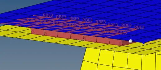
- Rear_truss_2 & Right_Rail_2 and Rear_truss_2 & Left_Rail_2:- Bolt Connector
Here we go to panel menu 2d--> connectors --> bolt --> select node and select two components, tolerence as 5mm and type: Bolt(general),--> create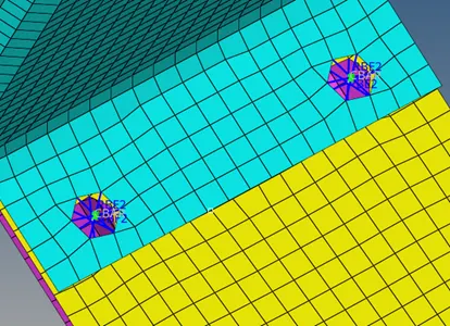
- Right_Rail_1 & Right_Rail_2 and Left_Rail_1 & Left_Rail_2:- Spot-weld with rigid and Spring Elements
Here we go to panel menu 2d--> connectors --> spot --> select nodes and number of layers as 2 and select two components, tolerence as 5mm and type: rigid or Spring and diameter as 5mm --> create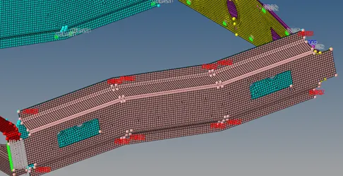
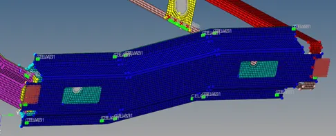
- And the remaning components are connected accordingly with different types of connectors as shown below
- Right_Rail_2 & Front_truss_1: Seam-Quad(angled+capped+L)
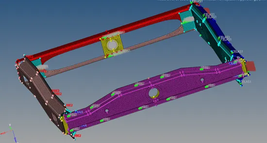
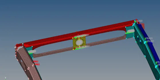
5. And finally we check for elements if ther is any loss in flow, we remesh those area and maintain mesh flow and the check for quality criteria.
Results:
Hence the given frame assembly is connected with appropriate connectors as spot welds, seam welds and bolt connectors and adhesives and rigid elements and spring elements.
Final CAD model: