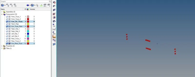
Week 9-Creation of 1D Connectors Challenge
AIM:
To Mesh the given component with the given "Element quality criteria" and to connect all the different components with appropriate "1D connectors" according to the above-specified places and specified connectors.
OBJECTIVE:
Target Element size - 5 Units
|
S.N |
Quality Criteria |
Value |
|
1 |
Aspect Ratio |
5 |
|
2 |
Skewness |
45 |
|
3 |
Warping |
15 |
|
4 |
Taper |
0.5 |
|
5 |
Min. Length |
2 Units |
|
6 |
Max. Length |
8 Units |
|
7 |
Min angle Quad |
45 |
|
8 |
Max angle Quad |
135 |
|
9 |
Min angle Tria |
30 |
|
10 |
Max angle Tria |
110 |
|
10 |
Tria % |
15 |
Create connector and Attach the various parts of the given model
1. Right_Rail_2 & Front_truss_1:- Seam-Quad(angled+capped+L)
2. Left_Rail_2 & Front_truss_1:- Quad elements
3. Front_truss_2, Front_truss_1 & Right_Rail_1:- Spot weld with 3 Layers and 5 mm Diameter
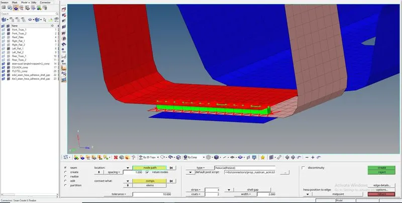
4. Front_truss_2, Front_truss_1 & Left_Rail_1:- Hexa (Adhesive)
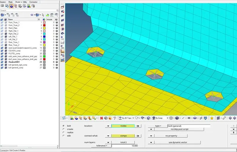
5. Rear_truss_2 & Right_Rail_2:- Bolt Connector
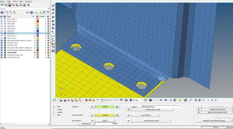
6. Rear_truss_2 & Left_Rail_2:- Bolt Connector
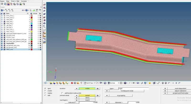
7. Right_Rail_1 & Right_Rail_2:- Spot-weld with Rigid Elements
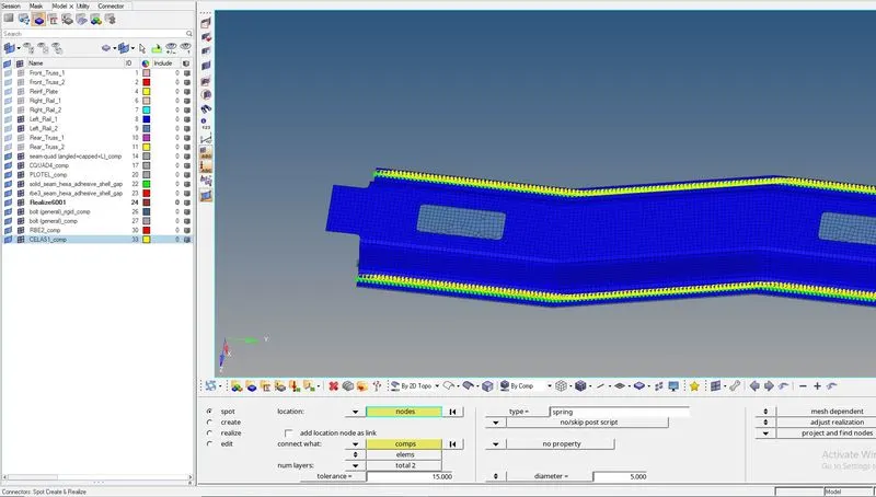
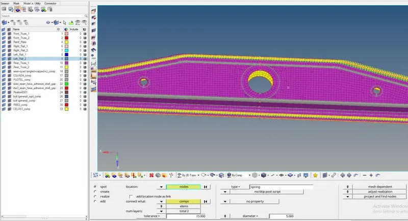
8. Left_Rail_1 & Left_Rail_2:- Spot-weld with Spring Elements
9. Rest all the component left Join them with suitable connectors
PROCEDURE:
MESHED COMPONENT WITH THE GIVEN ELEMENT QUALITY CRITERIA:
IMAGE-1:
IMAGE-2:
IMAGE-3:
IMAGE-4:
ATTACHING THE VARIOUS PARTS OF THE GIVEN MODEL USING APPROPRIATE SPECIFIED CONNECTORS:
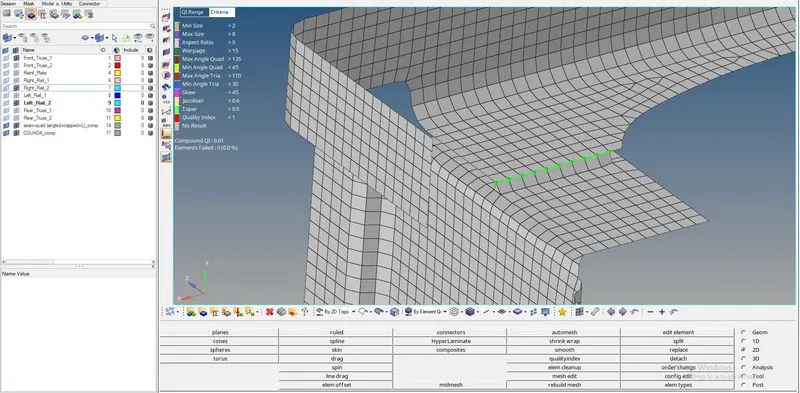
1. Right_Rail_2 & Front_truss_1:- Seam-Quad(angled+capped+L)
GOTO: '2D' >> 'Connectors' >> 'Seam' >> 'Location = node list' >> 'Type = Seam-Quad(angled+capped+L)'
IMAGE-1:

IMAGE-2:
2. Left_Rail_2 & Front_truss_1:- Quad elements
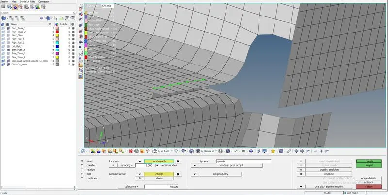
GOTO: '2D' >> 'Connectors' >> 'Seam' >> 'Location = node list' >> 'Type = Quads'
IMAGE-1:

IMAGE-2:
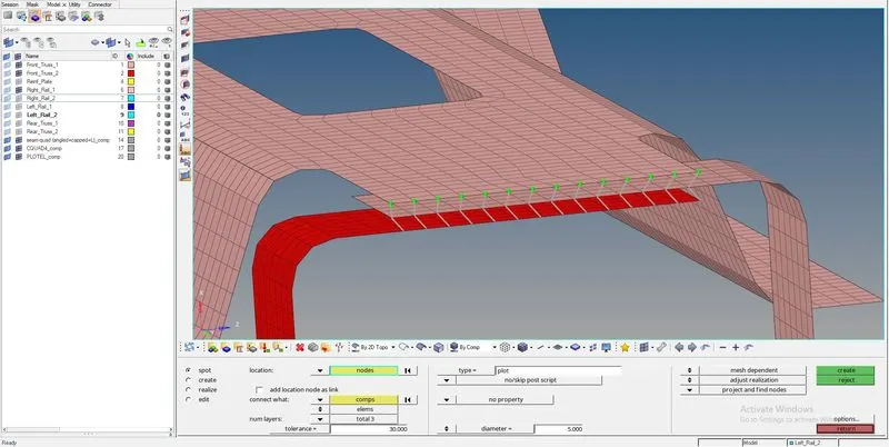
3. Front_truss_2, Front_truss_1 & Right_Rail_1:- Spot weld with 3 Layers and 5 mm Diameter
IMAGE-1:

IMAGE-2:
4. Front_truss_2, Front_truss_1 & Left_Rail_1:- Hexa (Adhesive)
IMAGE-1:

IMAGE-2: 4th connector between front truss 1 and left rail 1
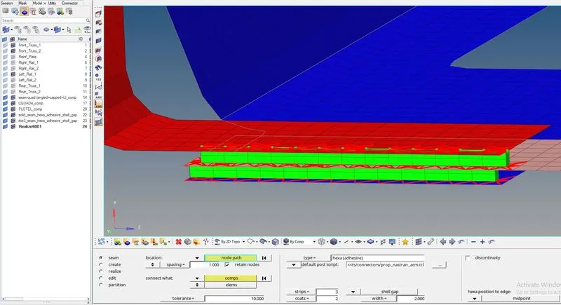
IMAGE-3: 4th connector between front truss 2 and front truss 1
5. Rear_truss_2 & Right_Rail_2:- Bolt Connector
IMAGE-1:
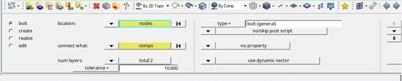
IMAGE-2:
6. Rear_truss_2 & Left_Rail_2:- Bolt Connector
IMAGE-1:
7. Right_Rail_1 & Right_Rail_2:- Spot-weld with Rigid Elements
IMAGE-1:

IMAGE-2:
8. Left_Rail_1 & Left_Rail_2:- Spot-weld with Spring Elements
IMAGE-1:

IMAGE-2:
9. Rest all the parts are connected with appropriate connectors as shown in the below images:
IMAGE-1:
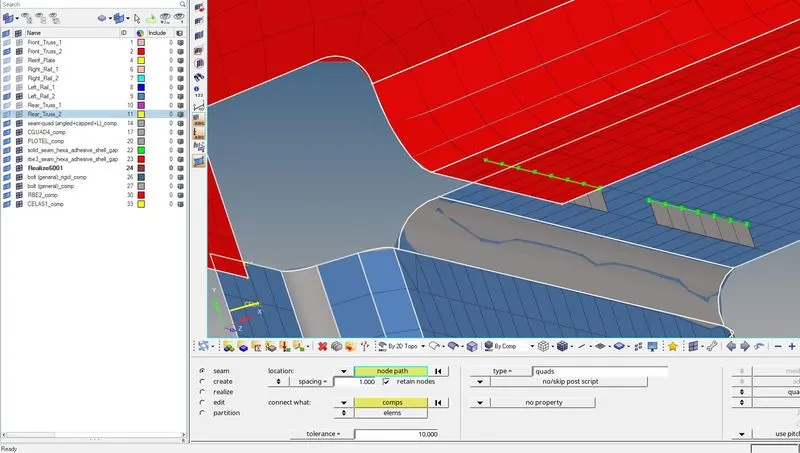
IMAGE-2:
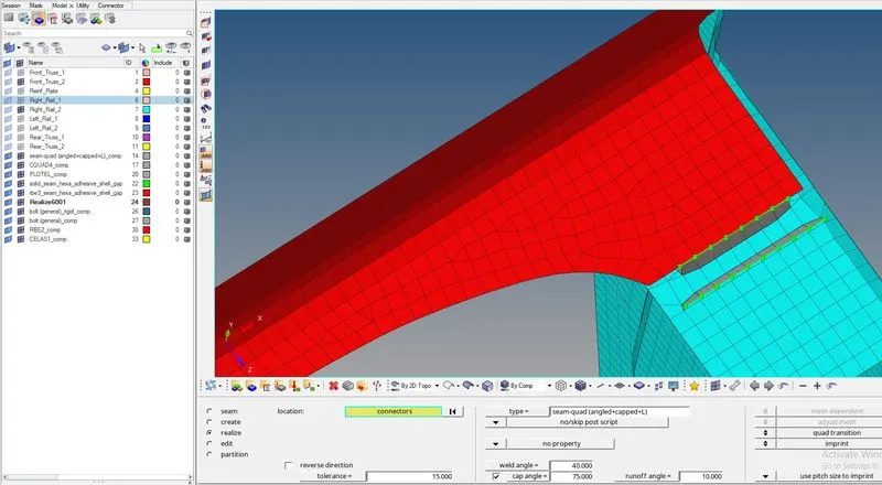
IMAGE-3:
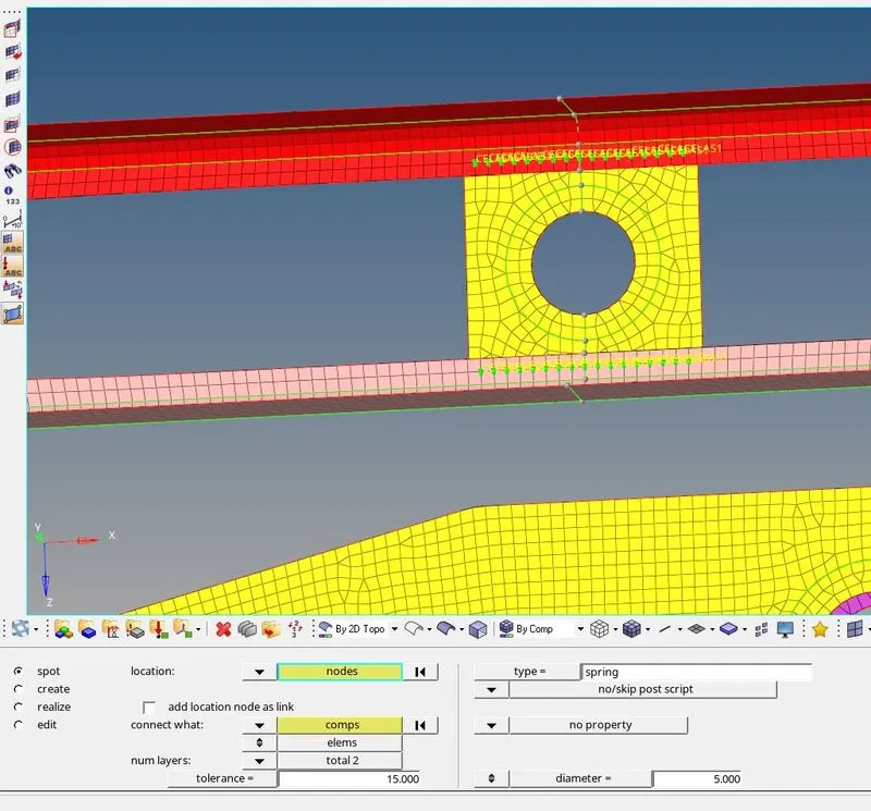
IMAGE-4:
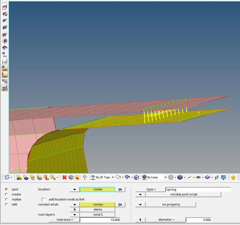
IMAGE-5:
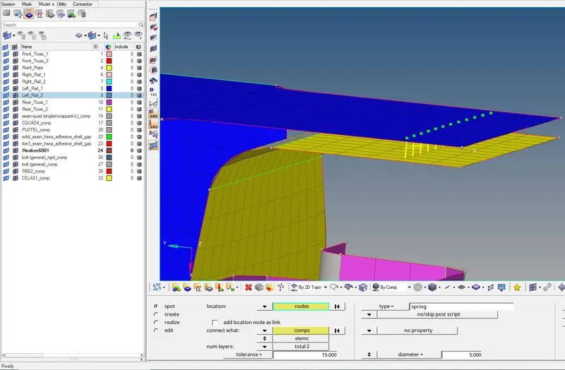
IMAGE-6:
DELETING ALL THE UNWANTED POINTS AS SHOWN IN THE BELOW IMAGE: