Week 9-Creation of 1D Connectors Challenge
For this challenge, you will have to mesh the given geometry. Provided below are the quality parameters that you have to follow.
Target Element size - 5 Units
|
S.N |
Quality Criteria |
Value |
|
1 |
Aspect Ratio |
5 |
|
2 |
Skewness |
45 |
|
3 |
Warping |
15 |
|
4 |
Taper |
0.5 |
|
5 |
Min. Length |
2 Units |
|
6 |
Max. Length |
8 Units |
|
7 |
Min angle Quad |
45 |
|
8 |
Max angle Quad |
135 |
|
9 |
Min angle Tria |
30 |
|
10 |
Max angle Tria |
110 |
|
10 |
Tria % |
15 |
Create connector and Attach the various parts of the given model
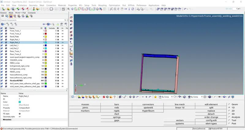
1. Right_Rail_2 & Front_truss_1:- Seam-Quad(angled+capped+L)
2. Left_Rail_2 & Front_truss_1:- Quad elements
3. Front_truss_2, Front_truss_1 & Right_Rail_1:- Spot weld with 2 Layers and 5 mm Diameter
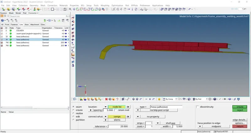
4. Front_truss_2, Front_truss_1 & Left_Rail_1:- Hexa (Adhesive)
5. Rear_truss_2 & Right_Rail_2:- Bolt Connector
6. Rear_truss_2 & Left_Rail_2:- Bolt Connector
7. Right_Rail_1 & Right_Rail_2:- Spot-weld with Rigid Elements
8. Left_Rail_1 & Left_Rail_2:- Spot-weld with Spring Elements
9. Rest all the component left Join them with suitable connectors
Component -Model
ANSWER - :
CONNECTORS -:
- Connectors allow you to create relationship between two nodes in a FEA model when we discretize a complex cad model.
- The connection can be simply by using rigids or some of them will be weld or bolt connection, which can impose more complicated constraints.
Different Types of Connectors -:
- Weld Connectors
- Bolt connectors
- Rigid Connectors
1. Realized Connectors -: Successful creation of connectors will be represented in Green color.
2. Unrealized Connectors -: Unrealized connector will be represented in yellow color.
3. Failed Connectors -: Failed Connectors connector will be represented in Red color.
Most Commonly Used Connectors in HyperMesh -:
- Seam Weld
- Spot Weld
- Adhesive
-Bolt Connectors