Week 9-Creation of 1D Connectors Challenge
Aim:
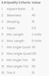
To mesh the given geometry for the below provided quality parameters.
Target Element size - 5 Units
Then, to create connectors on various parts of the given model
- Right_Rail_2 & Front_truss_1:- Seam-Quad(angled+capped+L)
- Left_Rail_2 & Front_truss_1:- Quad elements
- Front_truss_2, Front_truss_1 & Right_Rail_1:- Spot weld with 2 Layers and 5 mm Diameter
- Front_truss_2, Front_truss_1 & Left_Rail_1:- Hexa (Adhesive)
- Rear_truss_2 & Right_Rail_2:- Bolt Connector
- Rear_truss_2 & Left_Rail_2:- Bolt Connector
- Right_Rail_1 & Right_Rail_2:- Spot-weld with Rigid Elements
- Left_Rail_1 & Left_Rail_2:- Spot-weld with Spring Elements
- Rest all the component left Join them with suitable connectors
Procedure:
- The given model is opened in hyperworks using the Import geometry option
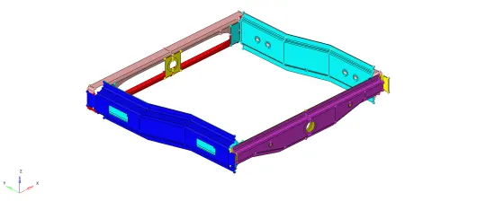
Figure 1 - Importing geometry
- Geometry cleanup:
-
Select Geometry --> Autocleanup --> select Surfaces --> Enter target elem size parameters as “5” in parameters --> Enter the given quality criteria in criteria --> select Autocleanup
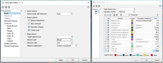
Figure 2 - Entering mesh parameters & quality criteria
-
The model after geometry cleanup is shown below:
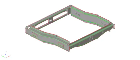
Figure 3 - After geometry cleanup
-
- Meshing
- Select 2D --> Automesh --> Enter element size as 5 --> Mesh type as mixed--> select the surfaces to mesh --> Select mesh
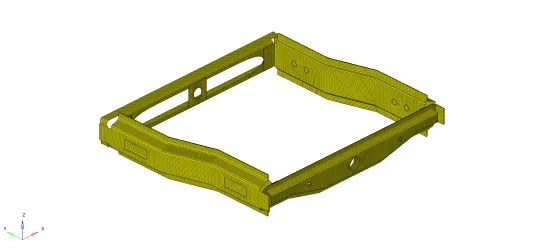
Figure 4 - Meshing of given model
By left or right clicking on the number on each edge of the model, the number of mesh points can be increased and decreased to achieve better mesh.
- Next, it is checked if the mesh generated passes the quality criteria. This is checked in the “quality index” option in 2D Tab. This is done as follows:
-
The quality parameters entered during autocleanup is present in this option too. By toggling the “fail” option in display threshold, the failed elements are visualized

Figure 5 - Quality index toolbox
-
The elements are cleaned up by using one of the options in the cleanup tools. The tools available are
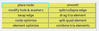
Figure 6 - Cleanup tools
- The final corrected 2D mesh for the component is as follows:
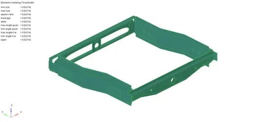
Figure 7 - Check mesh for the given model
-
- Select 2D --> Automesh --> Enter element size as 5 --> Mesh type as mixed--> select the surfaces to mesh --> Select mesh
-
Creating connectors:
- Connector 1 - Right_Rail_2 & Front_truss_1:- Seam-Quad(angled+capped+L):
- Select 1D/2D --> connectors --> seam --> change location as “nodelist / nodepath” --> select nodes --> Enter spacing as “5” --> check “retain nodes” --> select the components to connect as “comps” in connect what --> Enter the distance between the components in tolerance --> select type as “Seam-Quad(angled+capped+L)” --> create
- Check if the connector is realised properly (in green colour) and are not in red colour (improper connector realization)
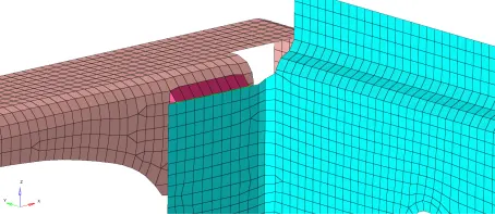
Figure 8 - Connector 1
-
Connector 2 - Left_Rail_2 & Front_truss_1:
-
Same steps as discussed in connector 1 are followed here, except the type, which is selected for this connector as “quads”
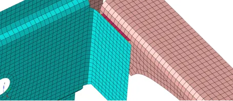
Figure 9 - Connector 2
-
-
Connector 3 - Front_truss_2, Front_truss_1 & Right_Rail_1:
-
Select 1D/2D --> connectors --> spot --> change location as “nodelist / nodepath” --> select nodes --> select the components to connect as “comps” in connect what --> Enter the distance between the components in tolerance --> select type as “weld” --> Enter diameter as “5” --> create
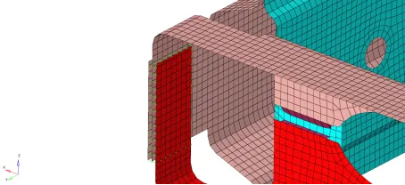
Figure 10 - Connector 3
-
-
Connector 4 -Front_truss_2, Front_truss_1 & Left_Rail_1:
-
Select 1D/2D --> connectors --> seam --> change location as “nodelist / nodepath” --> select nodes --> Enter spacing as “5” --> check “retain nodes” --> select the components to connect as “comps” in connect what --> Enter the distance between the components in tolerance --> select type as “Hexa (Adhesive)” --> Enter width as “5” create
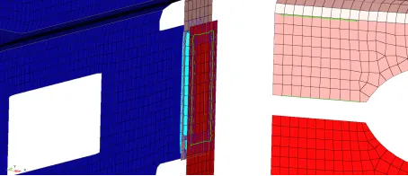
Figure 11 - Connector 4
-
-
Connectors 5 & 6 - Rear_truss_2 & Right_Rail_2, Rear_truss_2 & Left_Rail_2:
-
Select 1D/2D --> connectors --> bolt --> change location as “nodes” --> select nodes --> select the components to connect as “comps” in connect what --> Enter the distance between the components in tolerance --> select type as “bolt (general)” --> select ”create hole, if none” option, since there is no hole present in the geometry to be connected with bolt connector --> create create
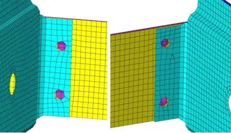
Figure 12 - Connectors 5 & 6
-
-
Connector 7 - Right_Rail_1 & Right_Rail_2:
- Select 1D/2D --> connectors --> spot --> change location as “nodelist / nodepath” --> select nodes --> select the components to connect as “comps” in connect what --> Enter the distance between the components in tolerance --> select type as “rigid” --> create
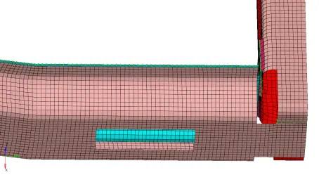
Figure 13 - Connector 7
- Select 1D/2D --> connectors --> spot --> change location as “nodelist / nodepath” --> select nodes --> select the components to connect as “comps” in connect what --> Enter the distance between the components in tolerance --> select type as “rigid” --> create
-
Connector 8 - Left_Rail_1 & Left_Rail_2:
-
Same steps as discussed in connector 7 are followed here, except the type is selected for this connector as “spring”
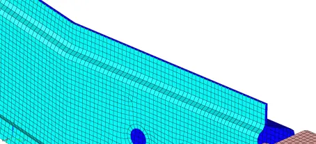
Figure 14 - Connector 8
-
-
The rest of parts of the model are assigned with the connectors discussed in the video material and articles. The final model is as follows:
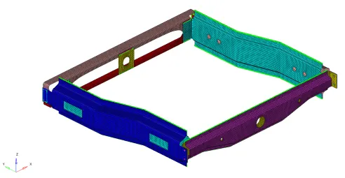
Figure 15 - Final model
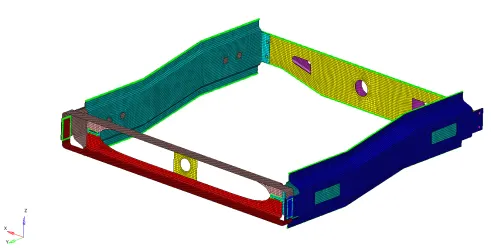
Figure 16 - Final model
-
The final model was also checked for quality criteria once again and the failed elements are corrected using the tools mentioned in step 3.
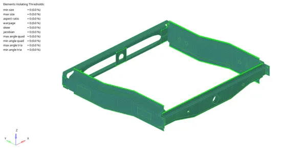
Figure 17 - Final model checked for quality criteria
- Connector 1 - Right_Rail_2 & Front_truss_1:- Seam-Quad(angled+capped+L):
Learning Outcomes:
- Meshing of given geometry for a given quality criteria
- Assign connectors for various parts of the model
Conclusion:
The given geometry is meshed, corrected for given quality criteria and assigned with connectors as per the challenge requirement.