Week- 5 - Solid meshing
Aim:
To check for the geometrical errors and mesh the Surfaces for the given Rear view mirror component, with the given 2D element Quality criteria.
Procedure:
Importing CAD model and geometrical error check:
1. Import the CAD geometry in ANSA. The faces of the geometry is not oriented properly.
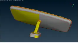
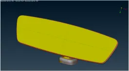
Figure 1 - Imported geometry of Hood model
2. Using Topo --> Orient --> Select/Visible, the faces of the geometry are oriented properly as shown below:
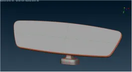
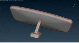
Figure 2 - Faces oriented properly
3. Using Topo --> Faces --> Topo, the geometry faces are stitched:
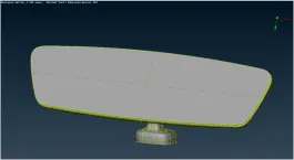
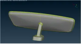
Figure 3 - Geometry after Topo operation
4. Using Tools --> Checks --> Geometry, the geometry of the model are checked for errors in geometry
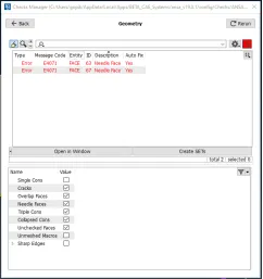
Figure 4 - Checking for errors in geometry
5. Select all the errors, right click and select “Fix” for fixing the errors automatically.
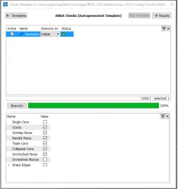
Figure 5 - Automatic Fixing of geometrical errors
Defeaturing using Batch mesh:
Using the batch meshing option, the defeaturing of the model was tried. Four batch meshing scenarios were created as shown below:
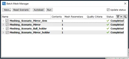
Figure 6 - Batch meshing
After the completion of batch meshing, the following model is obtained:
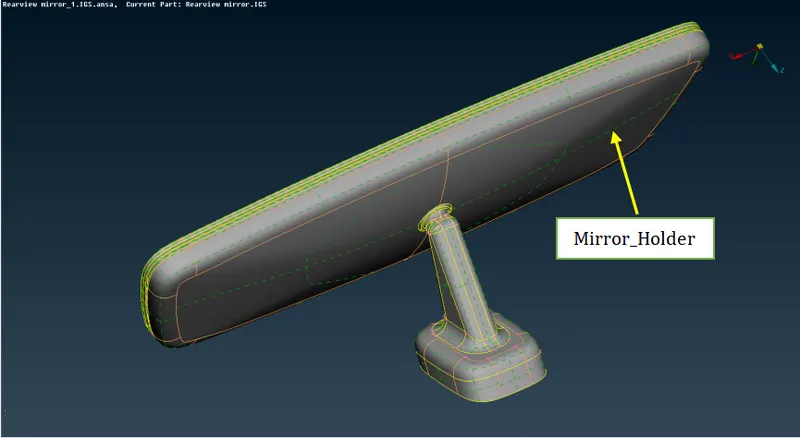
Figure 7 - Model defeatured using batch mesh
The defeaturing performed by ANSA for all the bodies except Mirror_Holder is observed to be acceptable. In the Mirror_Holder part, modifications are done on the cons that form the fillet edges (shown below). Using Topo --> Curves --> Middle, the middle of the two curves that form the fillet was obtained. Then, using Topo --> Curves --> Project, the curve was projected onto the face of the geometry. Using Mesh --> Macros --> Join, the fillet curves were removed.
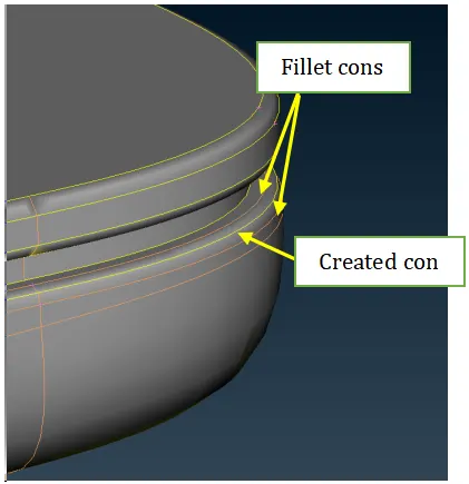
Figure 8 - Modification in Mirror_Holder
Mesh generation:
1. The given quality criteria for meshing the component is assigned in Utilities --> Quality Criteria option
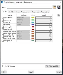
Figure 9 - Quality Criteria
2. The mesh parameters are also filled out and saved as .mpar data
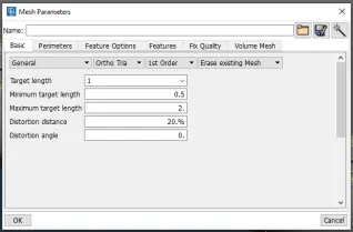
Figure 10 - Mesh parameter for the hood model
3. Perimeter Length is assigned to the component using Mesh --> Perimeters --> Length. Length is entered as 1.
4. Meshing is done using Spot Mesh option in the Mesh generation tab. For curved or round faces in the geometry, ortho tria was used and for flat surfaces, the tria elements were used
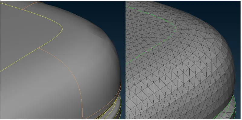
Figure 11 - Different mesh on rounded and flat faces of geometry
5. Select the faces to mesh and middle click to complete mesh generation
6. The meshes were checked for max and min length as per quality criteria. The elements that failed were corrected by using one of the below possibilities:
- Shell Mesh --> Reconstructis used to rearrange the mesh.
- Shell Mesh --> Smooth is used to smoothen the mesh and arrange it equally
- Elements --> Swap is used to rearrange the tria elements and hence better mesh flow
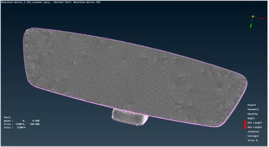
Figure 12 - Final mesh of Top Hood
Solid Mesh Generation:
1. Using Mesh --> Define --> Manual, the part of the model to which volume has to be created is selected
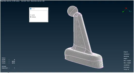
Figure 13 - Volume Definition
2. Property Help Window opens. In this window, New --> PSOLID is selected, appropriate Name for the volume is given. This step is repeated for all the other parts of the model
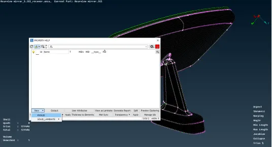
Figure 14 - Creating New solid in property tab
3. The defined volumes can be seen in Volume --> List option
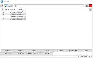
Figure 15 - Viewing defined volumes
The geometry is not yet meshed, hence is the Status “Unmeshed”. And the mesh algorithm type for which the geometry has to be meshed is not yet fixed. Hence is the data in column Type “Undefined”.
4. Right click on the ID 1 is performed and option Remesh is selected. This opens a window to select the mesh algorithm. For this model, TetraFEM is chosen.
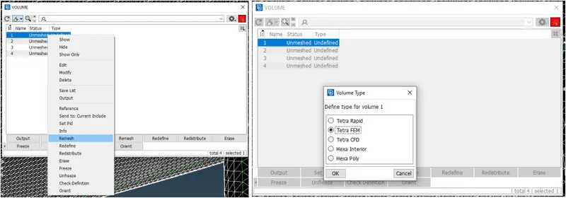
Figure 16 - Volume Mesh definition
5. After the mesh was created, none of the elements failed for Tet Collapse
6. The final meshed model is as follows:
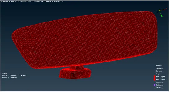
Figure 17 - Solid meshed model
Learning Outcomes:
1. Solid Meshing of a model with tetra elements
2. Usage of combined ortho tria and tria elements for reducing the number of elements in the model without compromising its quality
Conclusion:
Thus, the given rear view mirror model has been checked for the geometrical errors and solid mesh with tetra elements were created satisfying the given 2D element Quality criteria.
Model Link - https://drive.google.com/file/d/18gO1BMQoRSOA1-ApT8DUv8sxhMQ5lBoW/view?usp=sharing