Week 3 - 2D meshing for sheet metal
Aim:
To create mid surface for all the components in the give hood model after checking the geometrical errors and mesh the created mid surface with the given element quality criteria and mesh parameters.
Procedure:
Importing CAD model and geometrical error check:
- Import the CAD geometry in ANSA.
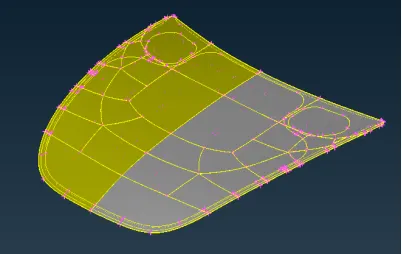
Figure 1 - Imported geometry of Hood model - Using the Faces --> Orient --> Visibleoption, the orientation of the faces are corrected.
The outside faces are oriented to be grey in colour and inside faces yellow.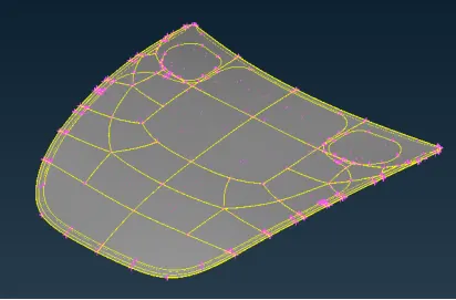
Figure 2 - Correcting the orientation of faces of the model - Using Tools --> Checks --> Geometry, the geometry of the imported model is checked for errors in geometry
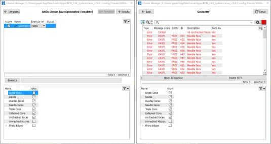
Figure 3 - Checking for errors in geometry - Select all the errors, right click and select “Fix” for fixing the errors automatically.
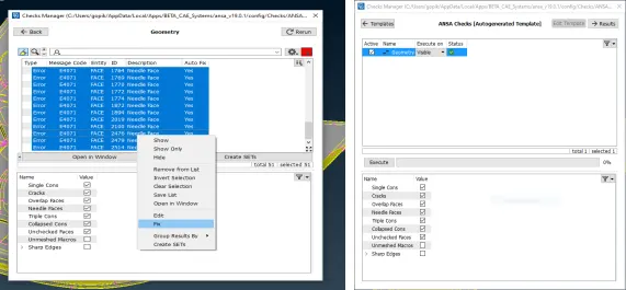
Figure 4 - Automatic Fixing of geometrical errors - After performing the geometry check, the mid surface is to be generated. Before that, the thickness of the sheet is measured at different points on all the bodies in hood to ensure that thickness is uniform, so that mid-surface can be created using Offset option
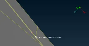
Figure 5 - Verify the thickness of bodies in hood model
Creating Mid surface for the model:
- Based on the thickness of different bodies of the hood model, it has been split into three different model. Properties would be assigned in Properties Tab for the models accordingly the geometry has been split into 3 models.
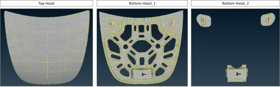
Figure 6 - Different bodies of hood model - Using Faces --> Offset --> Faces option, the mid surface creation has been done
- Select the face, to which mid surface has to be created and enter the offset distance. The offset distance is half the thickness of sheet metal. Using the Feature option and by entering a suitable feature angle, multiple faces can be selected
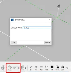
Figure 7 - Assiging offset distance for mid surface creation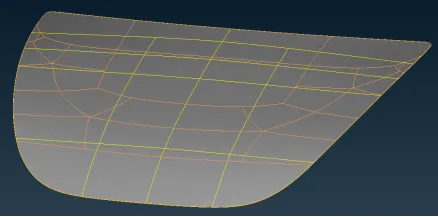
Figure 8 - Mid surface for Top Hood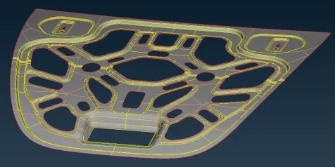
Figure 9 - Mid surface for Bottom_Hood_1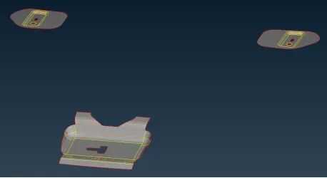
Figure 10 - Mid surface for Bottom_Hood_2 - After creating mid surface for all the bodies of the hood model, each of the three bodies were created with a PID in the Properties
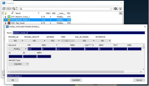
Figure 11 - Create PID for all bodies of hood model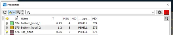
Figure 12 - Create PIDs for all the bodies of geometry
Mesh generation:
- The given quality criteria for meshing the component is assigned in Utilities --> Quality Criteria option
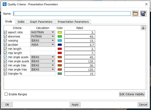
Figure 13 - Quality criteria - Using the Save option, the quality criteria is saved so that next time when the model is loaded, the criteria can be loaded directly and hence reducing the effort of entering the values for every session
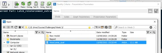
Figure 14 - Loading saved quality criteria - The mesh parameters are also filled out and saved as .mpar data
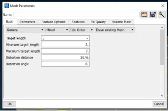
Figure 15 - Mesh parameter for the hood model - Perimeter Length is assigned to the component using Mesh --> Perimeters --> Length. Length is entered as 5.
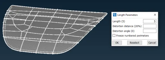
Figure 16 - Assign perimeter length for the model - The model is cut symmetrically before the mesh is generated
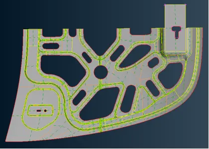
Figure 17 - Symmetrical half of Bottom_Hood_1 - In the Mesh Generation tab, appropriate option for mesh generation is selected. Mostly Best or Free or Spot Mesh
-
Select the faces to mesh and middle click to complete mesh generation
-
Shell Mesh --> Reconstruct is used to rearrange the mesh. This helps in removing tria elements or mesh not generated properly
-
Shell Mesh --> Smooth is used to smoothen the mesh and arrange it equally. This option does not rearrange the mesh. But adjusts only the size of the mesh along the selected area
-
Grids --> Paste, Elements --> Split, Elements --> Swap are used to rearrange the tria elements and hence better mesh flow
-
In some regions, the model may have complex contours or the space between two contour lines maybe so close that the element created would be less than the minimum element size as per the quality criteria.
In such cases, the contour lines of the geometry is altered using Faces --> Cut (in Topo mode) or Macros --> Join (In Mesh mode).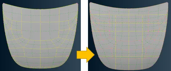
Figure 18 - Modification of contour in Topo mode
Using the options in Curves (Topo mode) or Macros --> Cut (In Mesh mode), necessary contour lines can be created to ensure mesh flow
Figure 19 - Adjustment of contour to ensure mesh flow -
After Meshing, using Utilities --> Transform --> Copy --> Symmetry tab --> Mirror 3 Points plane --> Select 3 points on the model(Top, middle and bottom) --> Apply --> Finish to create the other symmetrical half of the model. Using Faces --> Topo, the both halves of the model are stitched together
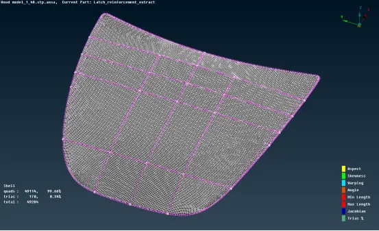
Figure 20 - Final mesh of Top hood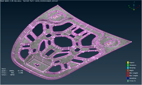
Figure 21 - Final mesh of Bottom_Hood_1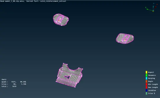
Figure 22 - Final mesh of Bottom_Hood_2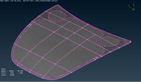
Figure 23 - Final mesh of complete hood model
Learning Outcomes:
- Mid surface creation for sheet metal components
- Handling of tria elements using Split, Swap and Paste options
- Modification and creation of geometrical contours using Faces --> Cut option, options in Curves Tab, Cons Tab, .etc., to ensure proper mesh flow
- If the geometry is symmetric, then one half of the model can be meshed and the other half can be mirrored using Mirror option in Transform tab
Conclusion:
Midsurface has been created for the given hood model. The geometry was checked for geomterical errors . The mesh has been generated as per the given quality criteria, in which the percentage of tria elements has been maintained at 1.25%, which is lesser than the value given in the criteria