Week 9-Creation of 1D Connectors Challenge
Question:
Mesh the given geometry. Provided below are the quality parameters that you have to follow.
Target Element size - 5 Units
|
Sr. No. |
Quality Criteria |
Value |
|
1 |
Aspect Ratio |
5 |
|
2 |
Skewness |
45 |
|
3 |
Warping |
15 |
|
4 |
Taper |
0.5 |
|
5 |
Min. Length |
2 Units |
|
6 |
Max. Length |
8 Units |
|
7 |
Min angle Quad |
45 |
|
8 |
Max angle Quad |
135 |
|
9 |
Min angle Tria |
30 |
|
10 |
Max angle Tria |
110 |
|
10 |
Tria % |
15 |
Create connectors and attach the various parts of the given model:
1. Right_Rail_2 & Front_truss_1:- Seam-Quad (angled+capped+L)
2. Left_Rail_2 & Front_truss_1:- Quad elements
3. Front_truss_2, Front_truss_1 & Right_Rail_1:- Spot weld with 2 Layersand 5 mm Diameter
4. Front_truss_2, Front_truss_1 & Left_Rail_1:- Hexa (Adhesive)
5. Rear_truss_2 & Right_Rail_2:- Bolt Connector
6. Rear_truss_2 & Left_Rail_2:- Bolt Connector
7. Right_Rail_1 & Right_Rail_2:- Spot-weld with Rigid Elements
8. Left_Rail_1 & Left_Rail_2:- Spot-weld with Spring Elements
9. Rest all the component left Join them with suitable connectors.
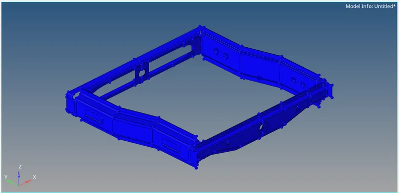
Fig1.1: Model under study.
Solution:
Procedure:
There are some basic steps involved in order to mesh the given component as per the quality requirements which are as follows:
I]
Firstly delete all the solids from the given component.
For deleting solids:
Goto => Tool => delete => solids => all => 'delete entity'
II]
Extract the midsurface of the component under study.
For extracting midsurface:
Goto => Geometry => midsurface => extraction option: skin offset => auto extraction: select surfaces => 'extract'
III]
Enter the quality criteria as per the quality requirements:
For defining quality criteria:
Goto => 2D => qualityindex => tick the paras => enter magnitude => 'return'
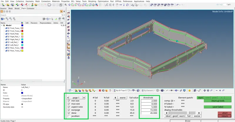
Fig1.2: Defining the quality parameters.
IV]
Setting the Element colour mode:
For setting the Element colour mode:
Goto => Element colour mode => 'By element quality'
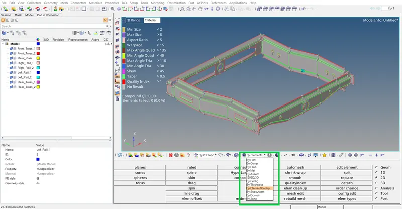
Fig1.3: Defining Element colour mode.
This mode helps us to check the elements of the given geometry as per the quality requirements. This makes the editing of the elements easy and convinient.
V]
Setting the Geometry colour mode:
For setting the Geometry colour mode:
Goto => Geometry colour mode => 'By 2D Topo'
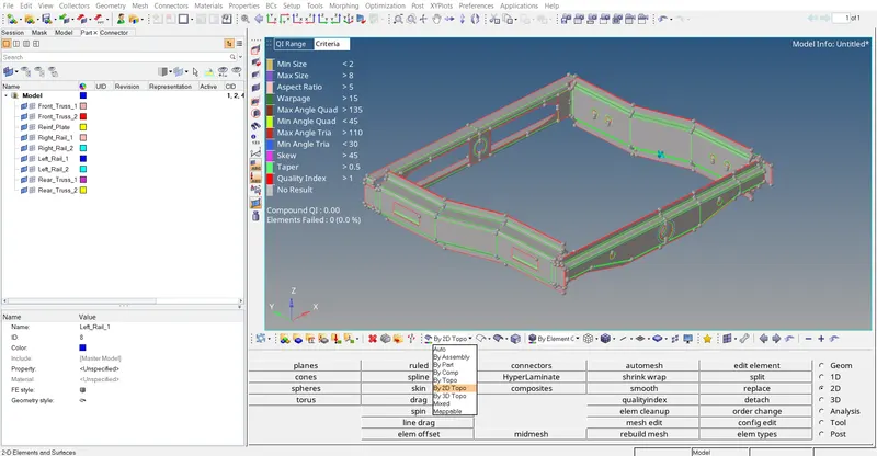
Fig1.4: Defining Geometry colour mode.
This mode helps us to check the construction and feature lines of the given geometry. This makes the toggling of the unwanted contruction lines easy and convinient during cleaning of the geometry.
VI]
Cleaning up the geometry:
For clean up:
Goto => Geometry => quick edit
Clean up the whole geometry before meshing. Toggle the unwanted construction lines, create lines and avoid creating regions of smaller areas.
VII]
Meshing of geometry:
For meshing:
Goto => 2D => automesh => select surfaces => element size: 5 units => 'mesh'
VIII]
Correcting meshing elements:
For correcting:
Goto => 2D => qualityindex => cleanup tools
Using cleanup tools we can optimize nodes, elements. Also smoothing of elements, spliting and combining can be done to better the quality of mesh.
IX]
Rebuild mesh:
For rebuilding:
Goto => rebuild mesh => select elements => 'rebuild'
Using the tools and rebulding command we will get mesh without any errors for the one half of the symmetry.
We can also use operations like replace nodes, node edit commands and element edit commands to build the proper mesh manually wherever necessary.
X]
Reflect the mesh:
For reflecting:
Select inner extract as current component.
Goto => Tool => reflect => elements: duplicate => current component => select N1,N2,N3,B => 'reflect'
XI]
Check for equivalence:
For equivalence check:
Goto => Tool => edges => elements: by attached => preview equivalence => equivalence => return
XII]
Deleting Free edges:
For deleting free edges:
Goto => Tool => edges => elements: by attached => 'find edges' => 'delete edges'
Now let's see how we are gonna create the 1D connectors.
Firstly create the materials.
Then create the properties for the components. Assign thickness of 2 mm to it.
Assign the material to the given property and finally assign the property to it's respective component.
1.
Right_Rail_2 & Front_truss_1:- Seam-Quad (angled+capped+L)
For seam weld:
Goto => 1D => connectors => seam => select nodes => spacing: 5 => select components => tol: 10 => type: seam-quad(angled+capped+L) => create
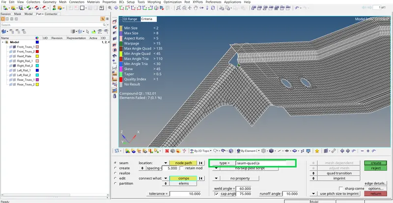
Fig1.5: Executing seam weld connector (seam-quad(angled+capped+L)).
Finally remesh the surfaces of the component to improve it's flow and quality.
2.
Left_Rail_2 & Front_truss_1:- Quad elements
For seam weld:
Goto => 1D => connectors => seam => select nodes => spacing: 5 => select components => tol: 10 => type: quads => create
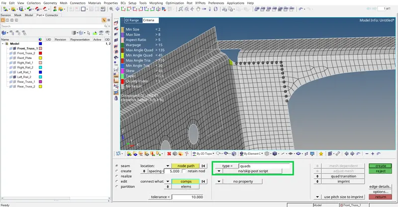
Fig1.6: Executing seam weld connector (Quads).
Finally remesh the surfaces of the component to improve it's flow and quality.
3.
Front_truss_2, Front_truss_1 & Right_Rail_1:- Spot weld with 2 Layers and 5 mm Diameter
For spot weld:
Goto => 1D => connectors => spot => select nodes => Layers: total 2 => select components => tol: 20 => dia: 5 => create
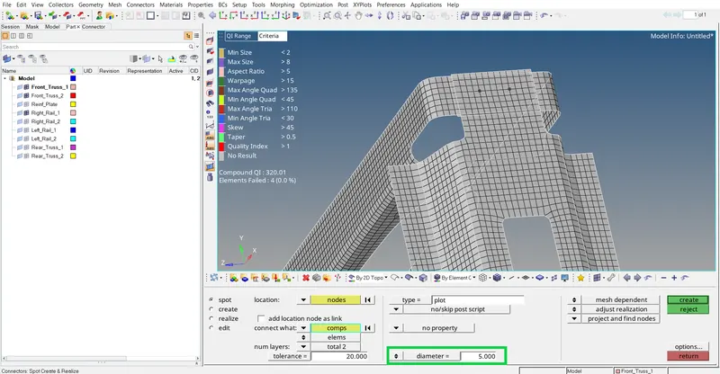
Fig1.7: Executing spot weld connector.
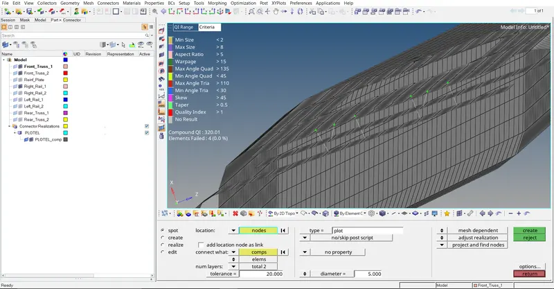
Fig1.8: Executing spot weld connector.
Finally remesh the surfaces of the component to improve it's flow and quality.
4.
Front_truss_2, Front_truss_1 & Left_Rail_1:- Hexa (Adhesive)
For Adhesives:
Goto => 1D => connectors => area => select elements => tol: 10 => select components => type: adhesives => create
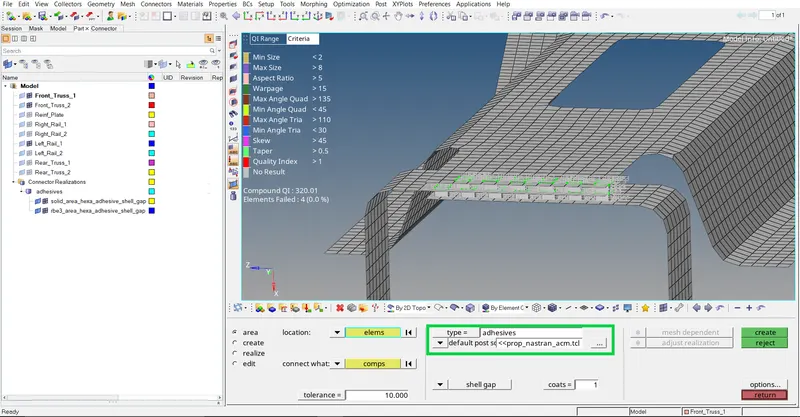
Fig1.9: Executing adhesive connector.
5.
Rear_truss_2 & Right_Rail_2:- Bolt Connector
For bolt connector:
Goto => 1D => connectors => bolt => select nodes => tol: 10 => select components => type: general => create hole, if none => create
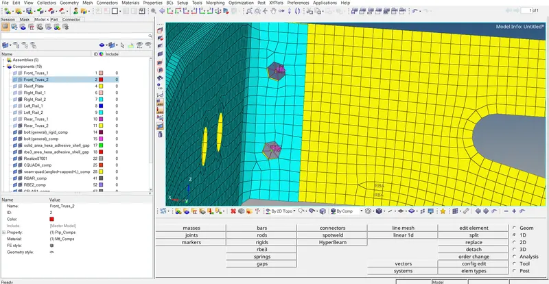
Fig1.10: Executing bolt connector.
Finally remesh the surfaces of the component to improve it's flow and quality.
6.
Rear_truss_2 & Left_Rail_2:- Bolt Connector
For bolt connector:
Goto => 1D => connectors => bolt => select nodes => tol: 10 => select components => type: general => create hole, if none => create
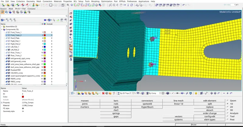
Fig1.11: Executing bolt connector.
Finally remesh the surfaces of the component to improve it's flow and quality.
7.
Right_Rail_1 & Right_Rail_2:- Spot-weld with Rigid Elements
For spot connector:
Goto => 1D => connectors => spot => select nodes => tol: 10 => select components => type: rigid => create
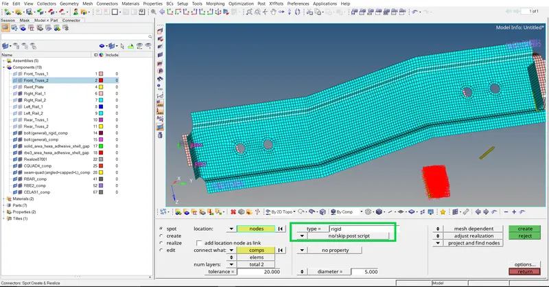
Fig1.12: Executing spot (rigid) connector.
Finally remesh the surfaces of the component to improve it's flow and quality.
8.
Left_Rail_1 & Left_Rail_2:- Spot-weld with Spring Elements
For spot connector:
Goto => 1D => connectors => spot => select nodes => tol: 10 => select components => type: spring => create
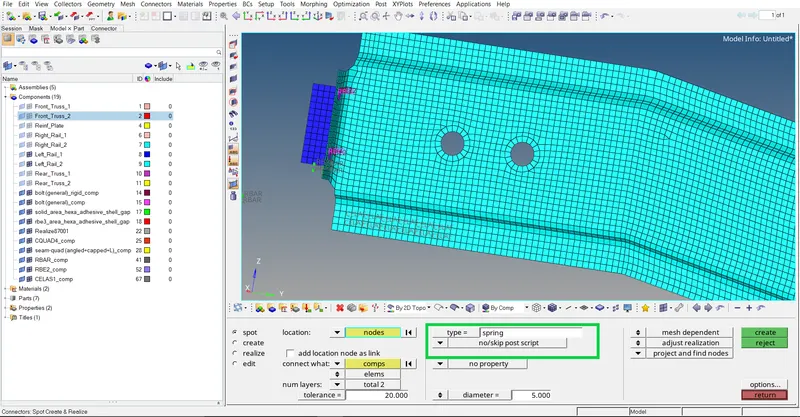
Fig1.12: Executing spot (spring) connector.
Finally remesh the surfaces of the component to improve it's flow and quality.