Week 9-Creation of 1D Connectors Challenge
Aim :- To mesh the given component within given quality parameters also creaate appropriate connectors wherever required as per given information.
Procedure :-
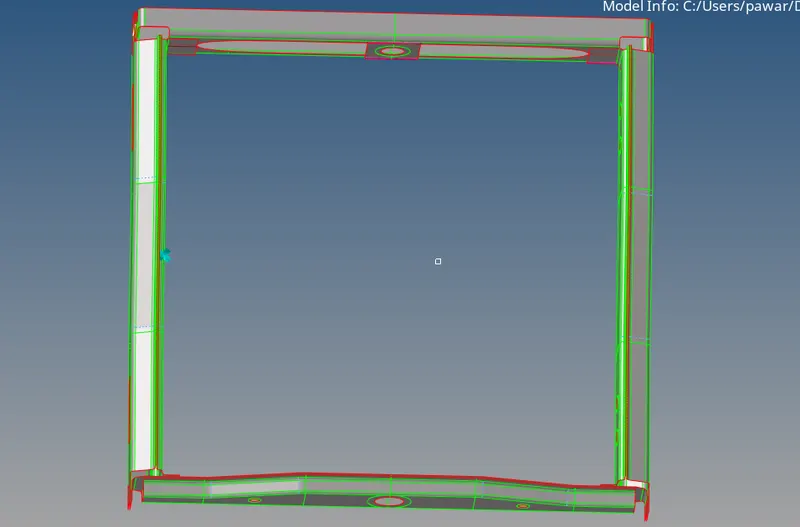
- First step we have to do is import given model in Hypermesh GUI. After importing the Frame assembly model first step we have to do is mesh the whole model.
- As given model contain 6 different component so we have to mesh the components seperately by using (2D - Auto mesh - Select the element size - select mesh type - select element displayed).
- Now we have to check whether mesh is within given quality parameters or not so we have to check whole model in (By element quality mode).
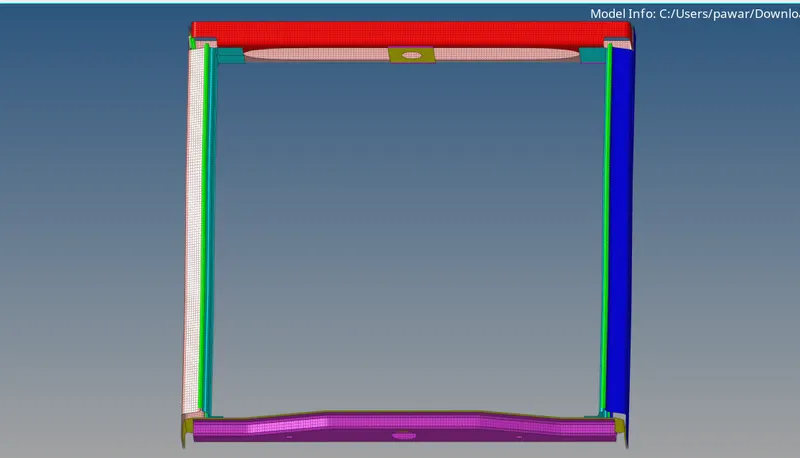
- Now elements which are not within given quality parameters we have to makke them proper by using element optimization, drag the tria, split etc cleanup tools.
- After removing all the quality errors we will go for connections provided for given assembly model.
- connections used for frame assembly are as follows:
1) Right_Rail_2 & Front_truss_1:- [Seam-Quad(angled+capped+L)]
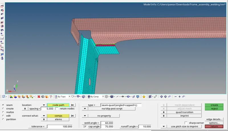
- For the proper connection between two components mesh should be proper on both the component.
- As per given parameter for Right_Rail_2 & Front_truss_1 we use Seam-Quad(angled+capped+L) connection by using (2D - Connectors - Seam - Type - Select the spacing - Select the tolerance value - Select the nodes - Select the components).
2) Left_Rail_2 & Front_truss_1:- Quad elements
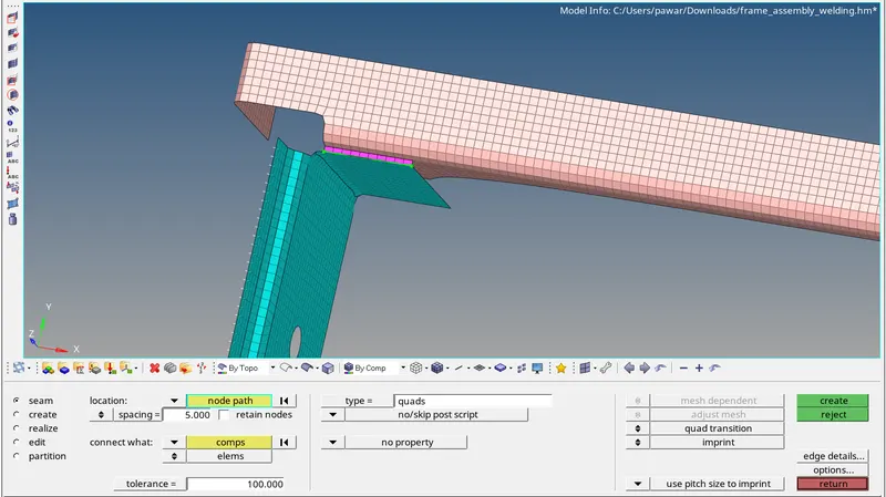
- As per given parameter for Left_Rail_2 & Front_truss_1 we use Quad connection by using (2D - Connectors - Seam - Type(Quad) - Select the spacing - Select the tolerance value - Select the nodes - Select the components).
3) Front_truss_2, Front_truss_1 & Right_Rail_1:- Spot weld with 2 Layers and 5 mm Diameter
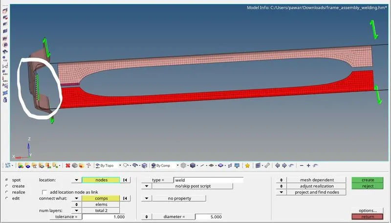
- As per given parameter for Front_truss_2, Front_truss_1 & Right_Rail_1 we use Spot weld connection by using (2D - Connectors - Seam - Type(Spot weld) - Select the spacing - Select the tolerance value - Select the nodes - Select the components).
4) Front_truss_2, Front_truss_1 & Left_Rail_1:- Hexa (Adhesive)
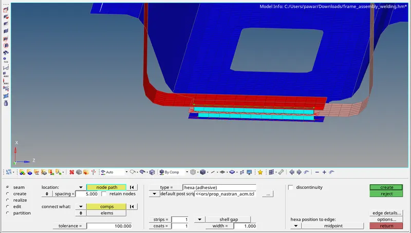
- As per given parameter for Front_truss_2, Front_truss_1 & Left_Rail_1 we use Hexa (adhesive) connection by using (2D - Connectors - Seam - Type(Hexa adhesive) - Select the spacing - Select the tolerance value - Select the nodes - Select the components).
- We have to do the same adhesive connection on both the side as we cannot do directly on three component at a time.
5) Rear_truss_2 & Right_Rail_2:- Bolt Connector
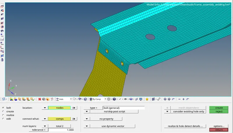
- As we required rigid connection between two components so we will go for bolt connection by using (2D - Connectors - Bolt - Type(Bolt general) - Select tolerance - Select the node - Select the components).
6) Rear_truss_2 & Left_Rail_2:- Bolt Connector
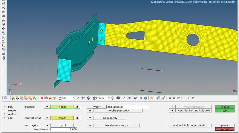
- As we required rigid connection between two components so we will go for bolt connection by using (2D - Connectors - Bolt - Type(Bolt general) - Select tolerance - Select the node - Select the components).
7) Right_Rail_1 & Right_Rail_2:- Spot-weld with Rigid Elements
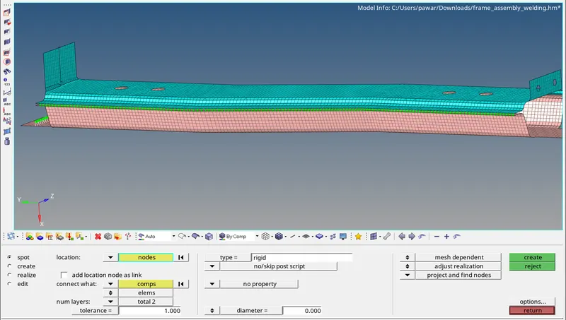
- As per given parameter for Right_Rail_1 & Right_Rail_2 we use Spot weld (Rigid elements) connection by using (2D - Connectors - Seam - Type(Spot weld) - Select the spacing - Select the tolerance value - Select the nodes - Select the components).
8) Left_Rail_1 & Left_Rail_2:- Spot-weld with Spring Elements
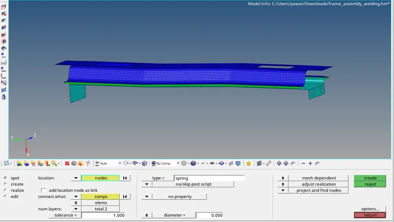
- As per given parameter for Left_Rail_1 & Left_Rail_2 we use Spot weld (Spring elements) connection by using (2D - Connectors - Seam - Type(Spot weld-Spring element) - Select the spacing - Select the tolerance value - Select the nodes - Select the components).
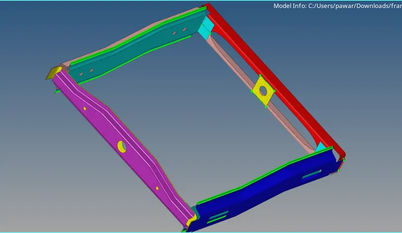
In this way we create all the connections which are required for given frame assembly model.
Conlcusion :-
In this challenge I learn about how to create different connectors for the model also use of all the connections and also possition of connections.