Week 9-Creation of 1D Connectors Challenge
AIM: To create 1D connectors to connect between different components.
OBJECTIVE:
To Create connector and Attach the various parts of the given model.
1. Right_Rail_2 & Front_truss_1:- Seam-Quad(
2. Left_Rail_2 & Front_truss_1:- Quad elements
3. Front_truss_2, Front_truss_1 & Right_Rail_1:- Spot weld with 2 Layers and 5 mm Diameter
4. Front_truss_2, Front_truss_1 & Left_Rail_1:- Hexa (Adhesive)
5. Rear_truss_2 & Right_Rail_2:- Bolt Connector
6. Rear_truss_2 & Left_Rail_2:- Bolt Connector
7. Right_Rail_1 & Right_Rail_2:- Spot-weld with
8. Left_Rail_1 & Left_Rail_2:- Spot-weld with
9. Rest all the component left Join them with suitable connectors
Quality parameters given:
Target Element size - 5 Units
|
S.N |
Quality Criteria |
Value |
|
1 |
Aspect Ratio |
5 |
|
2 |
Skewness |
45 |
|
3 |
Warping |
15 |
|
4 |
Taper |
0.5 |
|
5 |
Min. Length |
2 Units |
|
6 |
Max. Length |
8 Units |
|
7 |
Min angle Quad |
45 |
|
8 |
Max angle Quad |
135 |
|
9 |
Min angle Tria |
30 |
|
10 |
Max angle Tria |
110 |
|
10 |
Tria % |
15 |
CONNECTORS:
Connectors are geometric entities which are primarily used to represent the CAD geometric connection interms of FEA. Connectors can be created as a spot weld, seam weld, adhesives, bolts and masses. A realized connectors will be considered as the successful representation of CAD model in preprocessing and the connecting parts can be considered as connected.
PROCEDURE:
- Import and cleanup the geometry.
- Mesh the model with the given target element size and then proceed to connect the components as required.
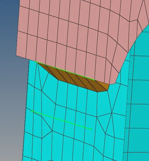
1. Right_Rail_2 & Front_truss_1:- Seam-Quad(
- In the connectors menu, the seam tool was used in which type of seam was selected as Seam-Quad(angled+capped+L).
- The nodes on one of the surfaces are selected.
- The spacing of 5 was kept as the mesh length was also 5.
- The components selected here are the components between which the connection is to be realized.
2. Left_Rail_2 & Front_truss_1:- Quad elements
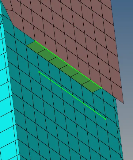
In the same tool as previous just need to change the type to Quads, so that it can be connected with quad elements.
3. Front_truss_2, Front_truss_1 & Right_Rail_1:- Spot weld with 2 Layers and 5 mm Diameter
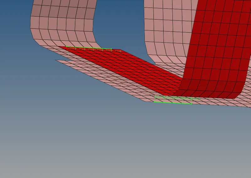
- In the 2D panel go to connectors and select spot in this panel select location as nodelist, assign spacing value with the target element size, give suitable tolerance and number of layers then select type as weld.
- Once the setting is done select the nodes and click middle button of the mouse and then select comps and create.
4. Front_truss_2, Front_truss_1 & Left_Rail_1:- Hexa (Adhesive)
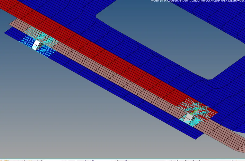
In the 2D panel go to connectors> seam>select location as nodelist and change type as hexa(adhesive) and then give values for spacing, and also check for retain nodes and enter values for tolerance and width, then select nodes and select components and create.
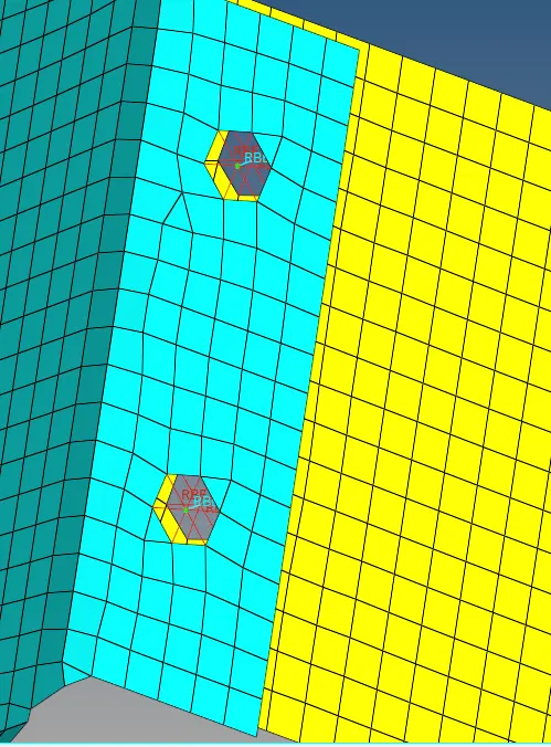
5. Rear_truss_2 & Right_Rail_2:- Bolt Connector
Go to connectors> bolt>location as nodelist and give spacing value check retain nodes and change type to bolt(general) then select node and components and create.
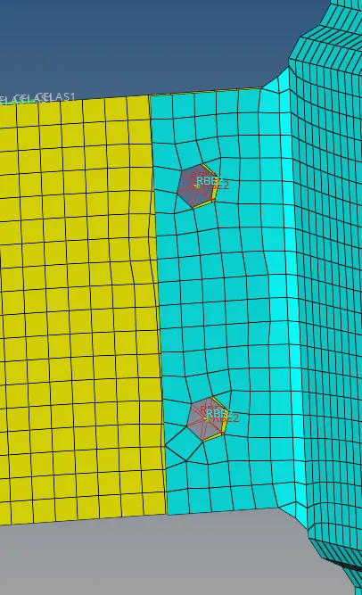
6. Rear_truss_2 & Left_Rail_2:- Bolt Connector
follow the same steps as in the previous one.
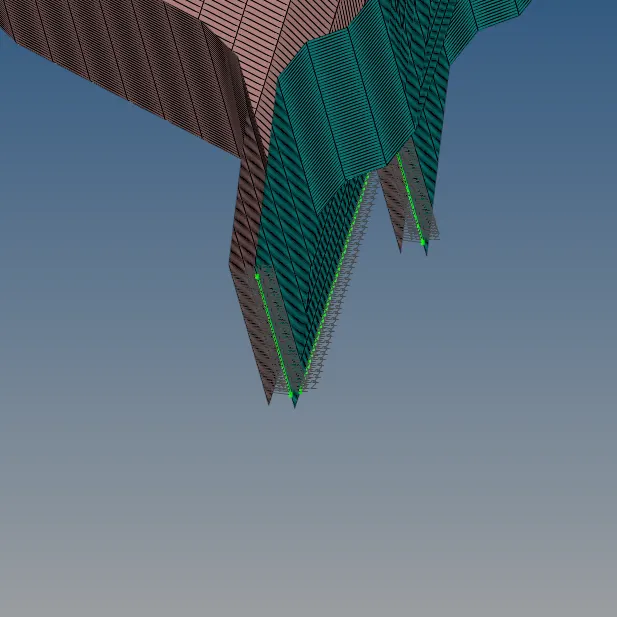
7. Right_Rail_1 & Right_Rail_2:- Spot-weld with
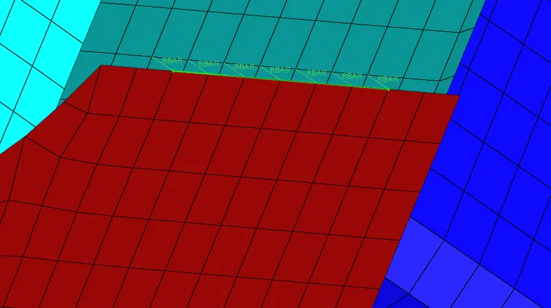
- In the 2D panel go to connectors and select spot in this panel select location as nodelist and assign spacing value with the target element size and check for retain nodes and give suitable tolerance and number of layers then select type as Rigids.
- Once the setting is done select the nodes and click middle button of the mouse and then select comps and create.
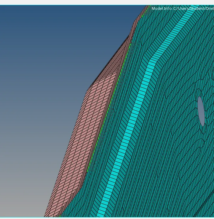
8. Left_Rail_1 & Left_Rail_2:- Spot-weld with
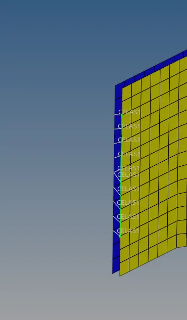
- In the 2D panel go to connectors and select spot in this panel select location as nodelist and assign spacing value with the target element size and check for retain nodes and give suitable tolerance and number of layers then select type as springs.
- Once the setting is done select the nodes and click middle button of the mouse and then select comps and create.
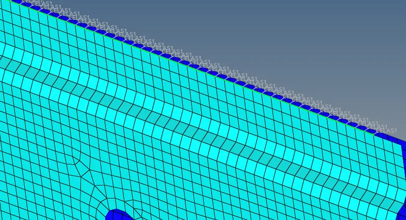

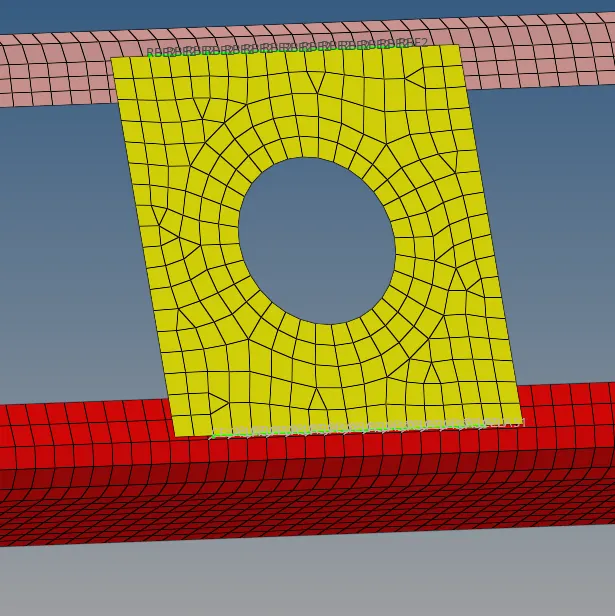
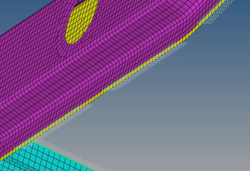
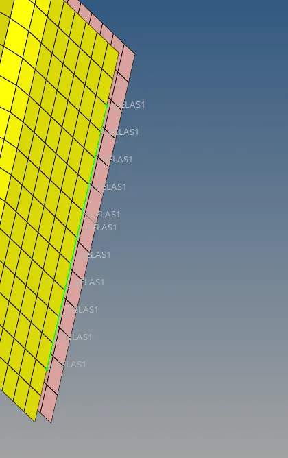
9. All left components have been connected with the spot weld connectors.
CONCLUSION:
I have learnt how to connect between components with the 1D connectors using Seam weld, Spot weld, and Bolts in Hypermesh through this challenge.