Week 9-Creation of 1D Connectors Challenge
Aim : To mesh the given geometry and to acheive the given mesh parameters
Objective : To mesh the given model and Creation of 1D Connectors to given geometry,moreover to perform mesh withgiven parameters.
* Given Model :
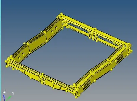
* The Above shown are given model
* Importing the given model :
* The given model are in hypermesh file it can be open the model
* The model are shown above
* Clicking to task bar and importing the model as shown below .

* Meshing
* By opening the model ,click to 2D and to automesh giving it to target element 5 further setting it to quads as shown below


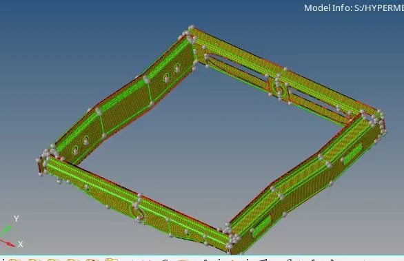
* After meshing ,checking the quality parameters as provided above .
* To check the quality parameters click to 2d and to quality index as shown below

* The mesh error are shown below
* Settingup the quality parameter value and check those errors
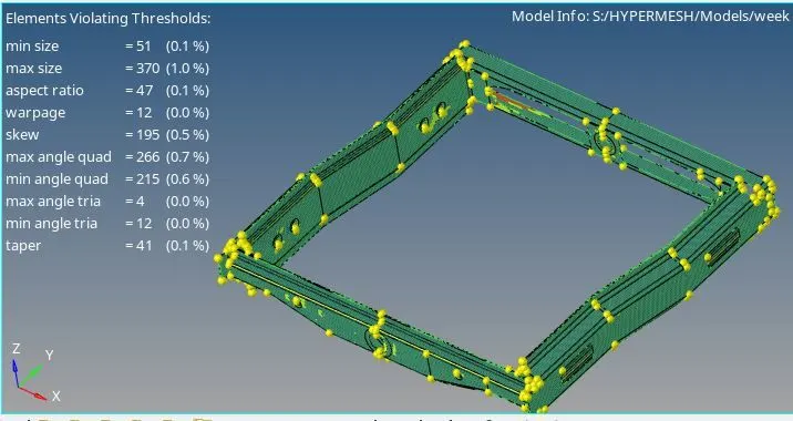
* After checking mesh errror , click to cleanup toools for correcting the mesh as shown below


* using above option the mesh errors are cleared.
* Creating connector and Attaching the various parts of the given model
1. Right_Rail_2 & Front_truss_1:- Seam-Quad(angled+capped+L)
* Model before seam welding
* The encircled region are to be welded as mentioned above
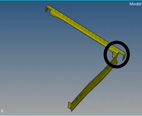
* Keeping above mentioned model part for veiw ,select 1D and to connector as shown below

* Selecting the connectors and click to seam ,furthermore selecting seam keeping spacing to 5 and type to quads with angled+capped+L as shown below


* after above ,selecting keeping it in nodelist,select the required compounds and click create
* By using above option the model are done which are shown below
* Model after seam welding
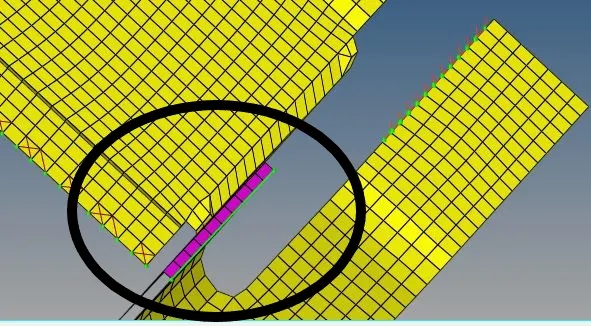
* The encircled region are seam welded region which is performed by above options
2. Left_Rail_2 & Front_truss_1:- Quad elements
* Model before quad welding
* The encircled region are to be welded as mentioned below
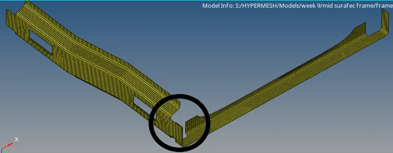
* Keeping above mentioned model part for veiw ,select 1D and to connector as shown below
* Selecting the connectors and click to seam ,furthermore selecting seam keeping spacing to 5 and type to quads with angled+capped+L as shown below
* after above ,selecting keeping it in nodelist and click to create
* after above ,selecting keeping it in nodelist,select the required compounds and click create
* By performing the above Option the Left_Rail_2 & Front_truss_1 Quad elements are done .
* The Model after quad welding
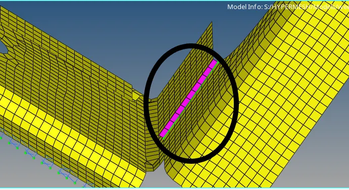
3. Front_truss_2, Front_truss_1 & Right_Rail_1:- Spot weld with 2 Layers and 5 mm Diameter
* Model before quad welding
* The encircled region are to be welded as mentioned below
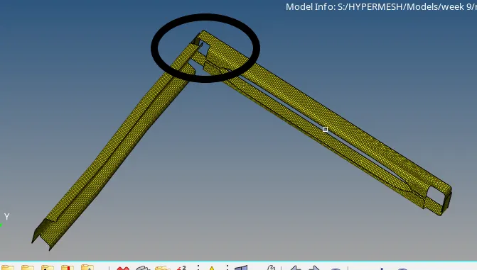
* Keeping above mentioned model part for veiw ,select 1D and to connector as shown below
* Selecting the connectors and click to spot weld.
* selecting spot weld ,entering the value 5 mm daimeter as given above i,e encircled below

* after above ,selecting keeping it in nodelist,select the required compounds and click create
* The Model after performing spot weld
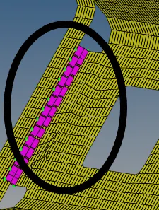
* The above encircled regions performed Front_truss_2, Front_truss_1 & Right_Rail_1Spot weld with 2 Layers and 5 mm Diameter
4. Front_truss_2, Front_truss_1 & Left_Rail_1:- Hexa (Adhesive)
* Model before spot weld (Hexa (Adhesive))
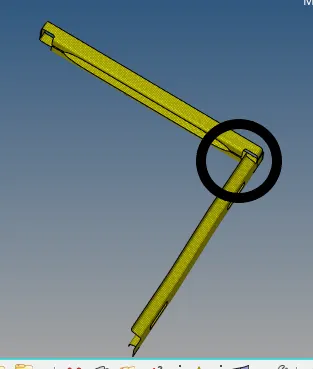
* Keeping above mentioned model part for veiw ,select 1D and to connector as shown below
* Selecting the connectors and click to spot weld.
* selecting spot weld ,entering the value 5 mm daimeter as given above i,e encircled below
* after above ,selecting keeping it in nodelist,select the required compounds and click create
* click to type ,select hexa spotweld as asked above and click to create as encircled below

* Model After spot weld (Hexa (Adhesive))
* The above encircled region are performed spot weld (Hexa (Adhesive)).
5. Rear_truss_2 & Right_Rail_2:- Bolt Connector
* Model before Bolt Connector
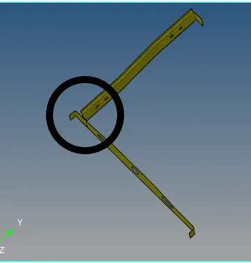
* Keeping above mentioned model part for veiw ,select 1D and to connector as shown below
* select bolt from connectors

* Select the required region which need to be bolt connect as show below
* Keeping it into bolt ,selecting the type as bolt as encircled below and if the surface doesnt has hole clicking it into create hole ,if none as sown below
* after above ,selecting keeping it in nodelist,select the required compounds and click create
* finnaly select the node required to be bolted and click create .

* model after performing bolt connections are shown below
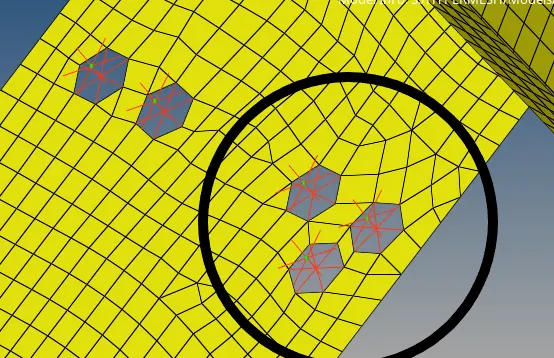
6.Rear_truss_2 & Left_Rail_2:- Bolt Connector
* Model before Bolt Connector
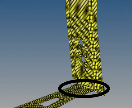
* Keeping above mentioned model part for veiw ,select 1D and to connector as shown below
* select bolt from connectors
* Select the required region which need to be bolt connect as show below
* Keeping it into bolt ,selecting the type as bolt as encircled below and if the surface doesnt has hole clicking it into create hole ,if none as sown below
* finnaly select the node required to be bolted and click create .
* model after performing bolt connections are shown below
* The encircled region are performed by bolt connection
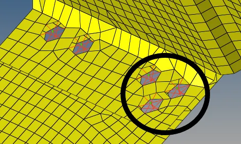
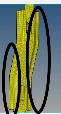
7. Right_Rail_1 & Right_Rail_2:- Spot-weld with Rigid Elements
* Model before quad welding
* The encircled region are to be welded as mentioned below
* Keeping above mentioned model part for veiw ,select 1D and to connector as shown below
* Selecting the connectors and click to spot weld.
* selecting spot weld ,click rigid as given below i,e encircled below

* after above ,selecting keeping it in nodelist and selecting the compounds , click to create
* The Model after performing spot weld
* The encircled region are done with Spot-weld with Rigid Elements
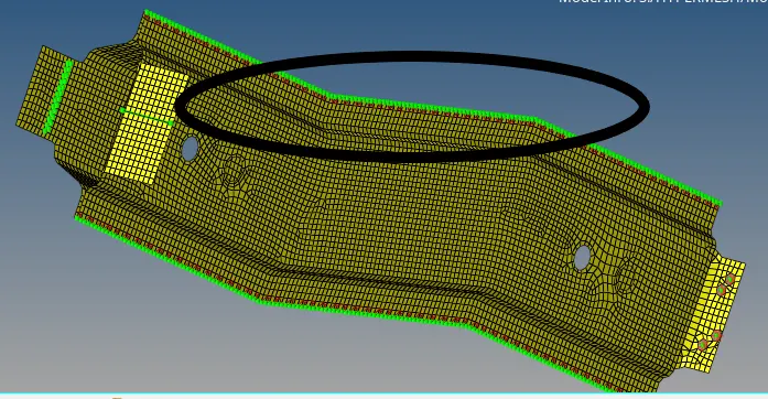
8. Left_Rail_1 & Left_Rail_2:- Spot-weld with Spring Elements
* Model before quad welding
* The encircled region are to be welded as mentioned below
* Keeping above mentioned model part for veiw ,select 1D and to connector as shown below
* Selecting the connectors and click to spot weld.
* selecting spot weld ,change the type as spring as given below i,e encircled below

* after above ,selecting keeping it in nodelist and selecting the compounds , click to create
* The Model after performing spot weld
* The encircled region are done with Spot-weld with Spring Elements
* The Model after performing spot weld
* Final geometry
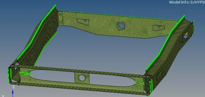
* The below shown geometry are completed with given qaulity parameters and given connectors .
* The model are attached below .
* The green colour represents the connectors .
* Conclusion : The given geometry can be meshed with given parameters and it can be seamed, spot welded and bolt connection ,the rest are joined with connectors.