Week 9-Creation of 1D Connectors Challenge
Aim: To perform meshing with given quality parameters and provide coneections to assembly
Target Element size - 5 Units
|
S.N |
Quality Criteria |
Value |
|
1 |
Aspect Ratio |
5 |
|
2 |
Skewness |
45 |
|
3 |
Warping |
15 |
|
4 |
Taper |
0.5 |
|
5 |
Min. Length |
2 Units |
|
6 |
Max. Length |
8 Units |
|
7 |
Min angle Quad |
45 |
|
8 |
Max angle Quad |
135 |
|
9 |
Min angle Tria |
30 |
|
10 |
Max angle Tria |
110 |
|
10 |
Tria % |
15 |
Objective: To perform meshing on the given assembly with above quality criteria and provide connections to the objects such that each and every connection is realized
Procedure:
1. The mesh was generated on each part of the assembly and then clean up was done on the based qulaity parameters
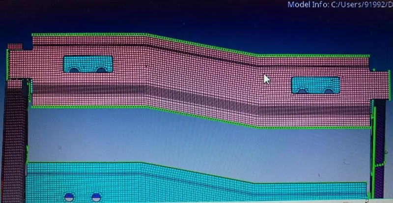
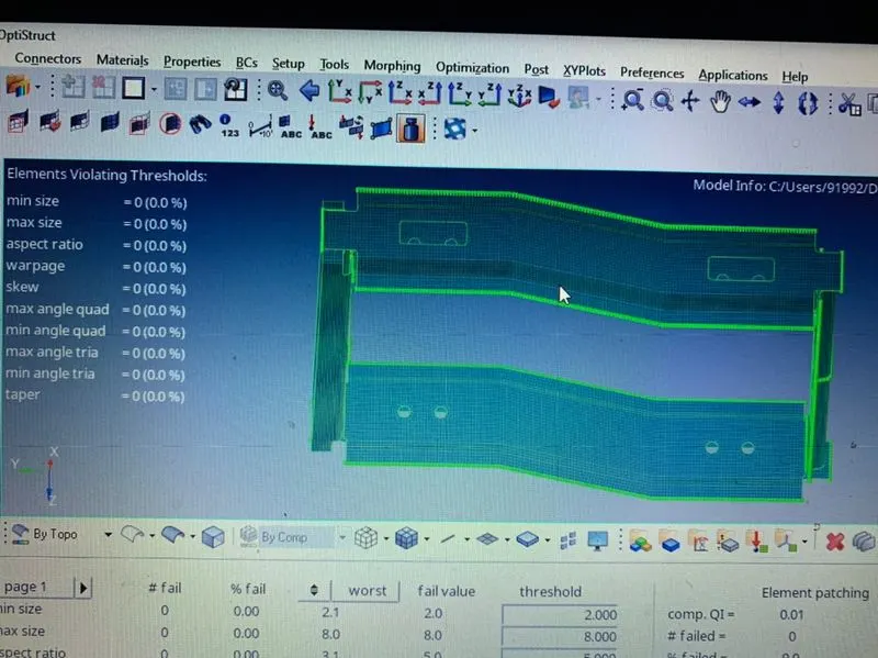
Fig : meshed parts Fig: Zero off elements
2.Then after meshing connection were provide to each and every part on the below given connection table
Create connector and Attach the various parts of the given model
1. Right_Rail_2 & Front_truss_1:- Seam-Quad(angled+capped+L)
2. Left_Rail_2 & Front_truss_1:- Quad elements
3. Front_truss_2, Front_truss_1 & Right_Rail_1:- Spot weld with 2 Layers and 5 mm Diameter
4. Front_truss_2, Front_truss_1 & Left_Rail_1:- Hexa (Adhesive)
5. Rear_truss_2 & Right_Rail_2:- Bolt Connector
6. Rear_truss_2 & Left_Rail_2:- Bolt Connector
7. Right_Rail_1 & Right_Rail_2:- Spot-weld with Rigid Elements
8. Left_Rail_1 & Left_Rail_2:- Spot-weld with Spring Elements
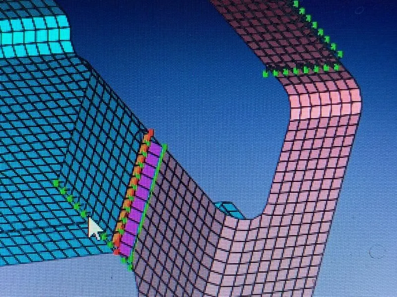
Fig: Right_Rail_2 & Front_truss_1:- Seam-Quad(angled+capped+L)
For providing the above connection connector tab was used and through seam option the Seam-Quad(angled+capped+L) was selected and tolerance was given on the basis of the distance between two components(this was used for all connection )
3. The connections were provided to each and every part and remaining connection were given on the user wish
4. The mesh was also improved after providing connections in such way that it matches the above criteria and mesh flow
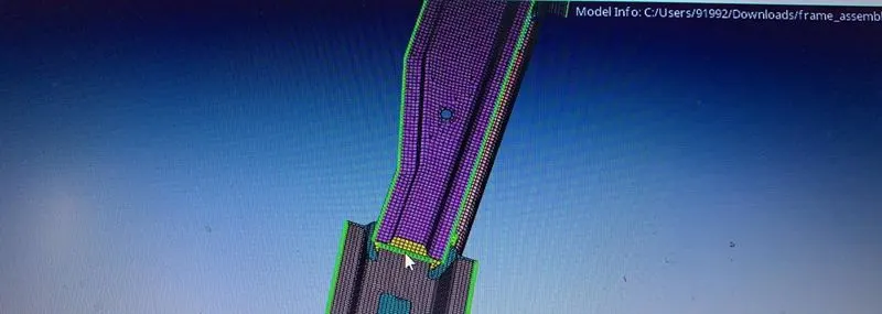
Fig : Disturbed mesh
5. The below are the attached images of the assembly according to axis wise to identify the given connections are properly realized
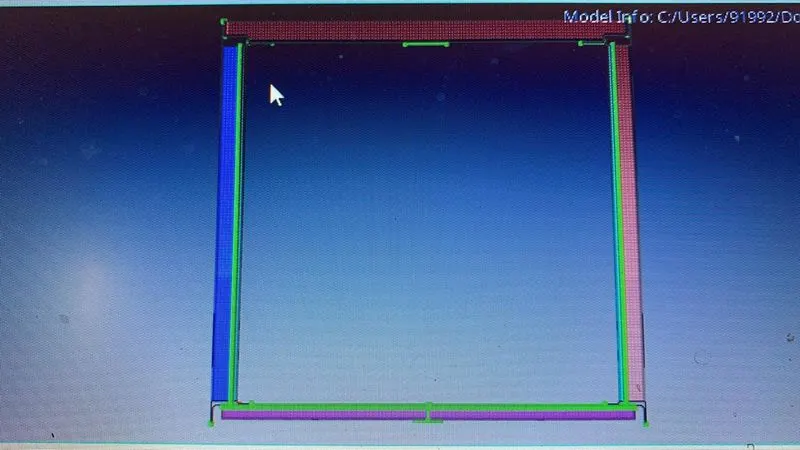
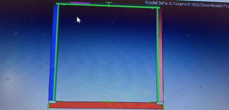
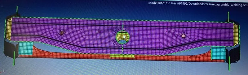
Fig :YX axis Fig: XY axis Fig :ZX axis
6. In this way the above given challenge was completed and finally the below model was assembled and realized
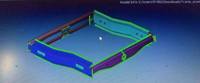
Fig : Final assembled image with connectors
Conclsuion: Hence proper mesh was created and connection were given to model so that it can undergo simulation
Learning outcomes: Hence came to learn about connections and realizing them and how to provide tolerance and how to clear mesh after giving conections