Week 9 - Creating connection for Rear door
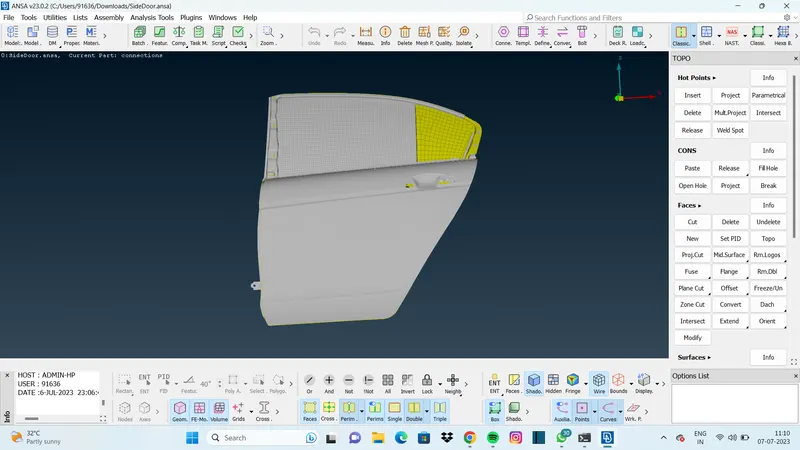
AIM : To perform suitable solid connection for the given rear door FE model by using different 1D elements.
CDA MODEL :
METHODS USED :
1. WASHER CONNECTION
2. TWO NODE CONNECTION
3. DOOR HANDLE CONNECTION
4. CENTER CRASHBEAM CONNECTION
5. CLUSTER CONNECTION
6. WINDOW SPOT WELD CONNECTION
1. WASHER CONNECTION:
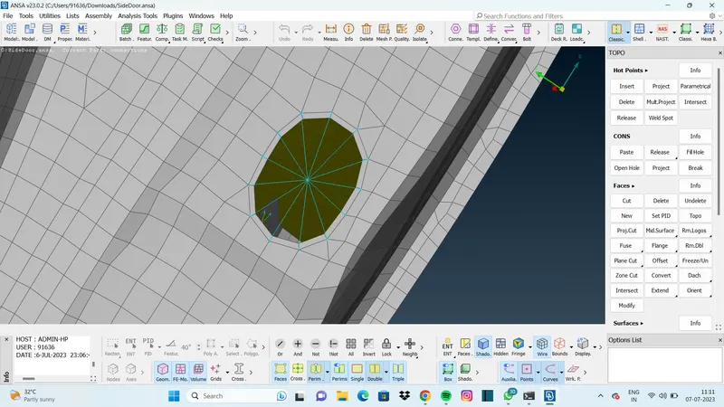
- The shown image was a single hole FE element.
- Instead taking a direct loop selection of nodes washer was created using function called zone cut.
- Then connection was succesfully made using RBE2 function.
2. TWO NODE CONNECTION :
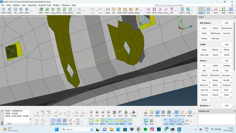
- For the door hinge washer need to be made for the one side because its an representation of bolt & nut connection.
- After creating all washer cut two node connection was made with 12345 CM.
3. DOOR HANDLE CONNECTION :
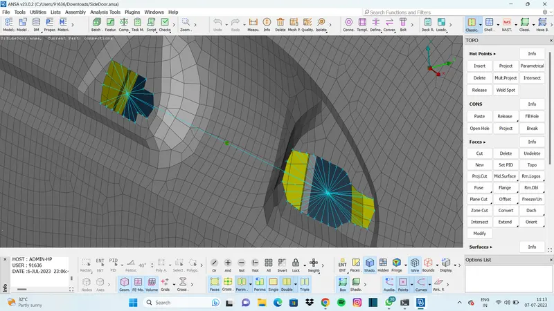
- For door handle each connection of holes was made seperately.
- Then many node RBE2 was used between those two seperate connections.
- By using CONMI function wight was defined.
4. CENTER CRASHBEAM CONNECTION :
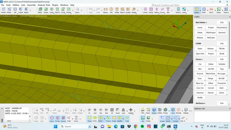
- For this connection RBE2 function was used to capture those two FE surface as one.
- before performing RBE2 3D point was made to capture those surfaces as spot weld but part id cannot able to create.
5. CLUSTER CONNECTION :
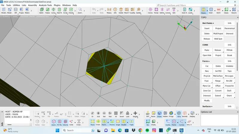
- There are 3 different FE surfaces instead capturing those 3 holes as bolt & nut connection all three holes nodes was selected using loop function to form as cluster with single master node.
- By doing this all three surfaces will be captured into one master node and makes it solid.
6. WINDOW SPOT WELD CONNECTION :
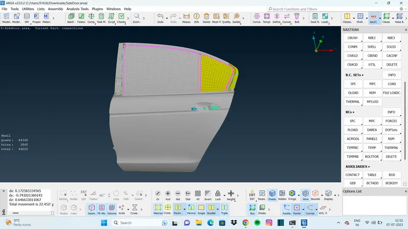
- For window glasses the conection was cannot be made due to in connection manager parts cannot able to define seperately.
- Because if any part is sleected to define p1, p2, p3 whole component is selected.
- so created a curve around the glass using CON2CURVE function and converted the curves into spot line.