mesh the frame assembly and create a connection at specific parts.
OBJECTIVE - To mesh the frame assembly and create a connection at specific parts.
PROCEDURE -
1. Meshing - First Import the frame assembly model and Mid surface is already given so perform a meshing by using option 2D >>Automesh >> element size 4 and then mesh.
2. Connection - next step is to provide connection to various part -
a. Seam-Quad(angled+capped+L) - Here seam weld is used to connect the component .First hide all the components and enable right rail 2 and front truss 1. Then give connection by using option 2D >> connectors >> seam >> type Seam-Quad(angled+capped+L) . Then select the node list on front truss and component to connect with remesh option. Increase tolerance value to 10 and click create and remesh the area for proper or smooth mesh flow.

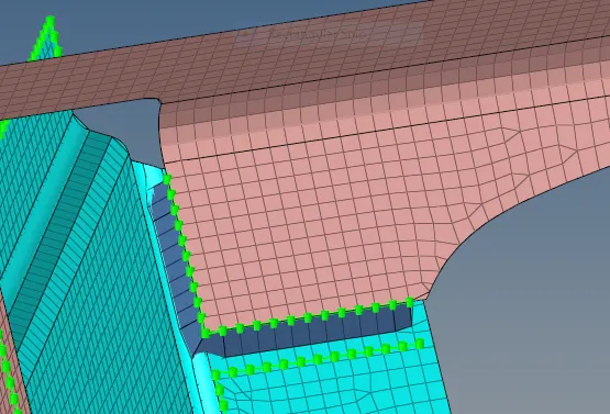
Fig. Seam-Quad(angled+capped+L) connection
b. Quad elements - First enable the Left rail 2 and front truss 1 part and then goes to 2D >> connectors >> seam >> type as Quad. select the node list on front truss and component to connect with remesh option and increase the tolerance value to 10 and click . create then connection is established.

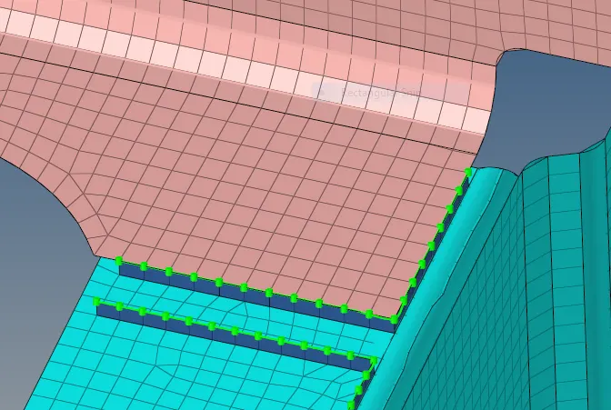
fig. Seam quad welding connection
c. Spot weld - Here the spot weld is used to connect the three components. first enable the only Front_truss_2, Front_truss_1 & Right_Rail_1 parts. now goes to 2D option >> connectors >> spot >> select type as weld and select the node from any of the top component and number of layer put 3 and diameter as 5 and rest of the option as mesh dependent and project and find nodes are kept as it is only.

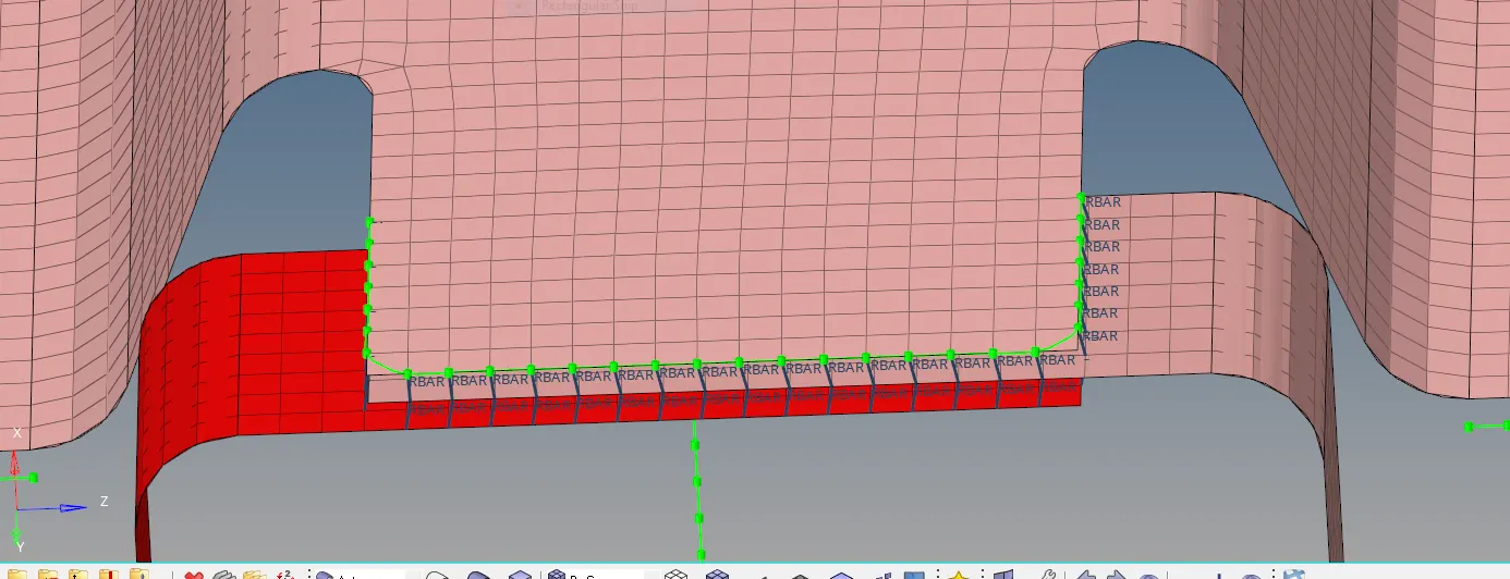
Fig. spot weld connection
d. Hexa (Adhesive) - Now enable only Front_truss_2, Front_truss_1 & Left_Rail_1 . then go to 2D >> connectors >> seam >> type as hexa adhesive. now Select the node list and choose all 3 component in comps. spacing as 4 and give tolerance to 10. coat and strip are kept as 1 . we also choose hexa position to edge into midpoint or positive or negative direction whichever nedded to obtained the cnnection.

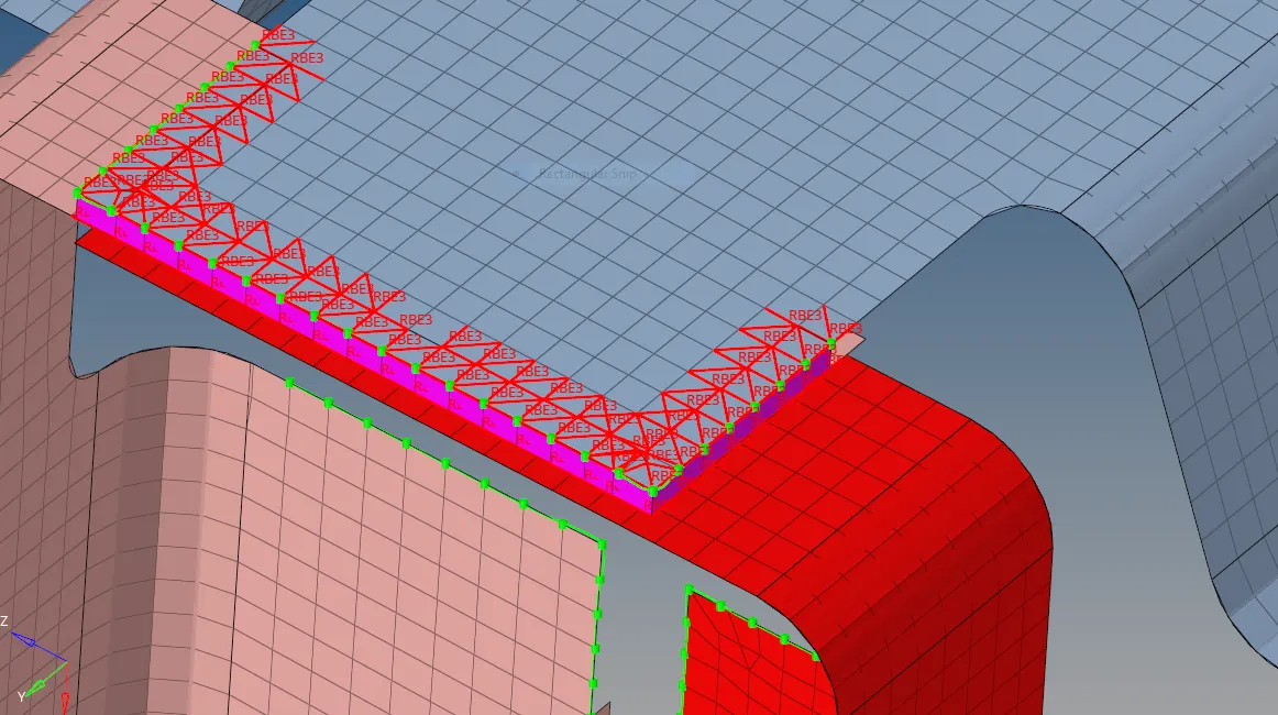
Fig. seam hexa adhesive connection
e. Bolt connection - the bolt connection is also a RBE2 based connection since they are consider to be rigid. here we have to deploy bolt connection at two place. Enable Rear_truss_2 & Right_Rail_2 and Rear_truss_2 & Left_Rail_2 and Go to 2D >> Connectors >> bolt >> select any one node under the location >> select the component >> layer as 2 >> Tolerance as 10 >> type of bolt General >> now select the create hole , if none because no hole present in that place and create .

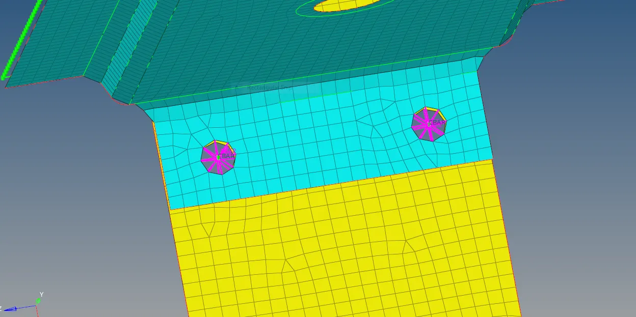
Fig. bolt connection
f. Spot-weld with Rigid Elements - Enable the Right_Rail_1 & Right_Rail_2 part and go to 2D >> connector >> spot >>type as rigid >> select the node >> select the component >> numb. of layer 2 >> give tolerance 10 and rest of the option as mesh dependent and project and find nodes are kept as it is only and then create.
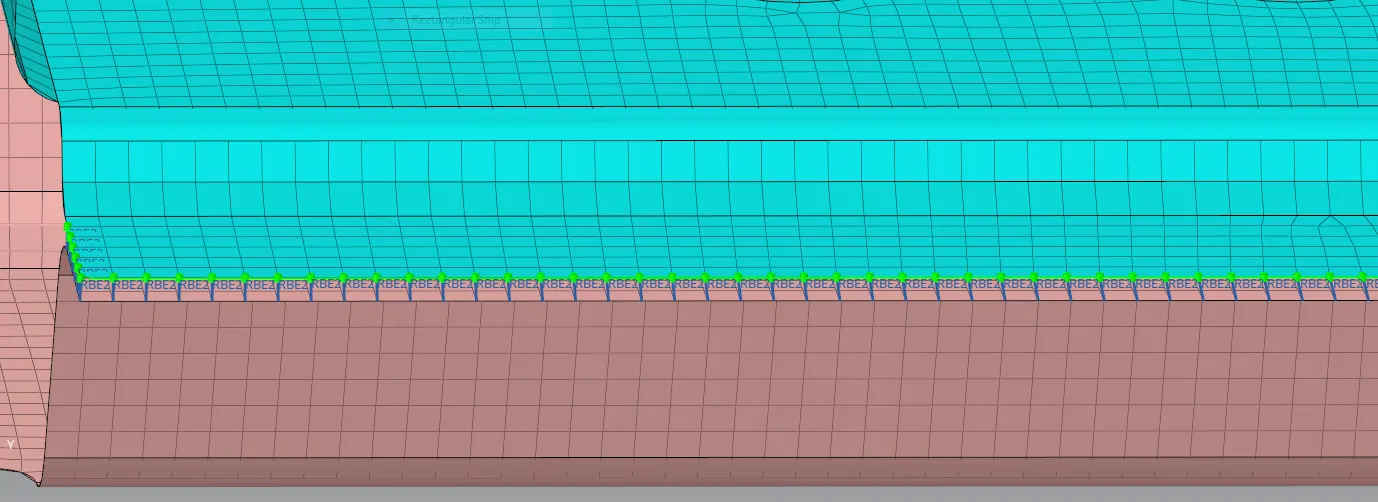
Fig. Rigid spot weld connection
g. Spot-weld with Spring Elements - Enable the Left_Rail_1 & Left_Rail_2 part and go to 2D >> connector >> spot >>type as rigid >> select the node >> select the component >> numb. of layer 2 >> give tolerance 10 and rest of the option as mesh dependent and project and find nodes are kept as it is only and then create.
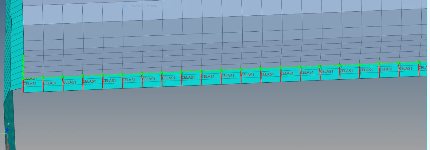
Fig. Spring spot weld connection
h. Rest all the component - Remaining components are connected by using the seam and spot bolt by following above steps.
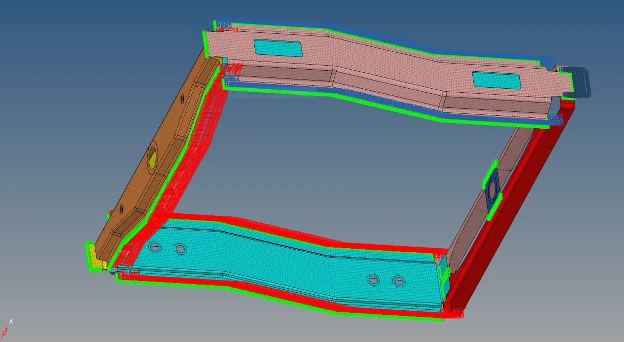
Fig. final view
CONCLUSION - All the required connection were made in the frame assembly welding .