Connection of rear door in Ansa
Objective : To perform the connection of rear door of a car with different connection techniques by using the option under NASTRAN deck.
Procedure :
1. Open the given rear door FE model in ansa by using the option FILE >> INPUT >> NASTRAN.
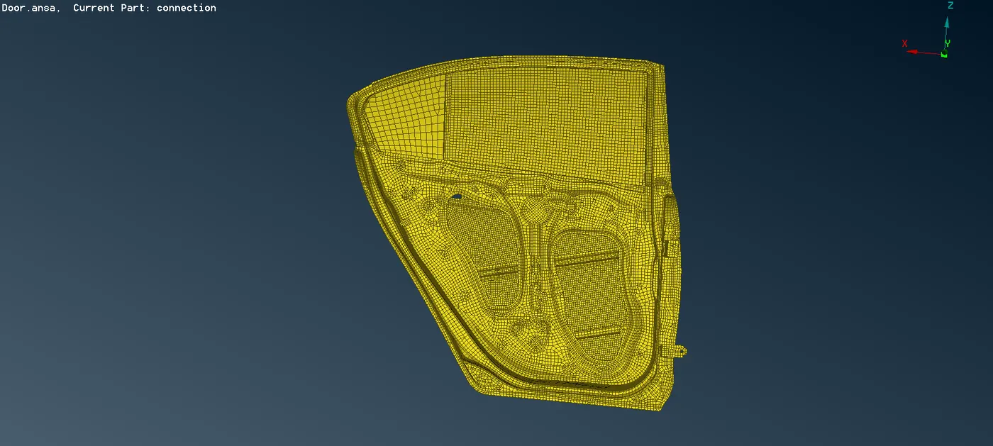
2. Assign a separate PIDs of various part of rear door.

3. Bolt connection : For holes that a bolt is to be used, give a COG point to one of the holes in parts that need to be connected. convert a COG point into bolt. use the connection manager and connect the parts by selecting the bolt feture.
now we will see how the connection is done
a. In the fig. you can see that four circle where connection are to be made, so we have to create a 3D point to make connection by TOPO >> POINTS >> ON COG.
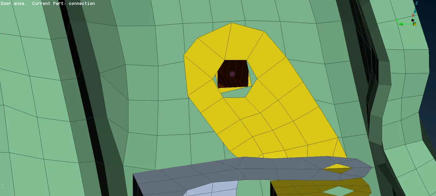
b. Now the 3D point are coverted into bolt connection by CONVERT >> BOLT.
c. Now clicking on connection and selecting the 3D point by middle click ,connection manager is opened.
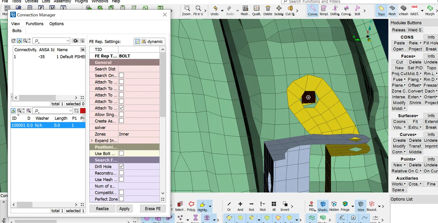
d. Now you can see the box option you will fill all the necessary information and then bolt connection is done. Max. 4 surfaces can be connected by this type of method.
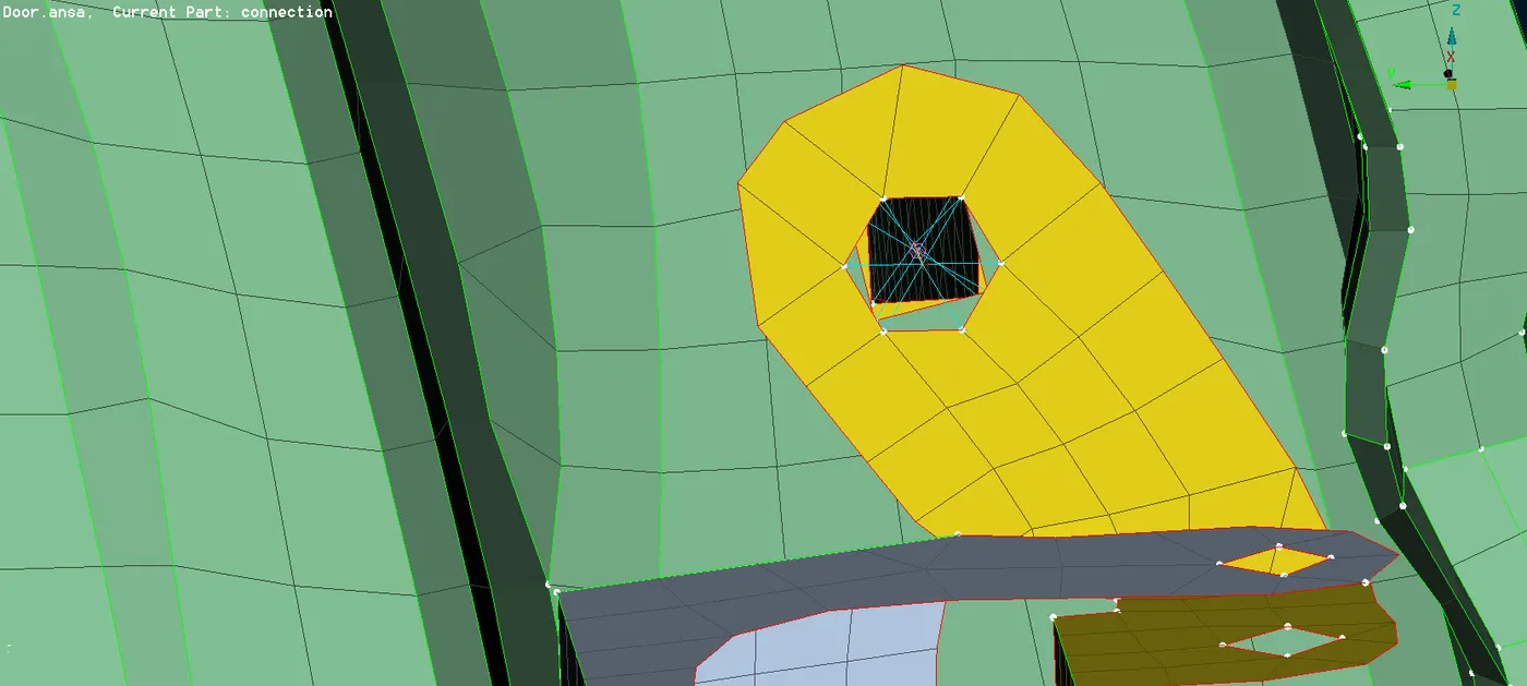
4. connection by RBE2 Element : NASTRAN >> ELEMENTS >> RBE2 >> MANY NODE can be used to create a cluster element for bolt hole when there are no different propertiesdefine to parts.
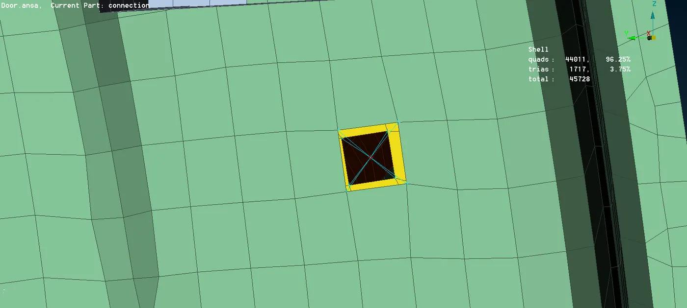
create ZONE CUT for bolt holes which is not connected to many parts. create RBE2 connection along with the washer elements around the hole.
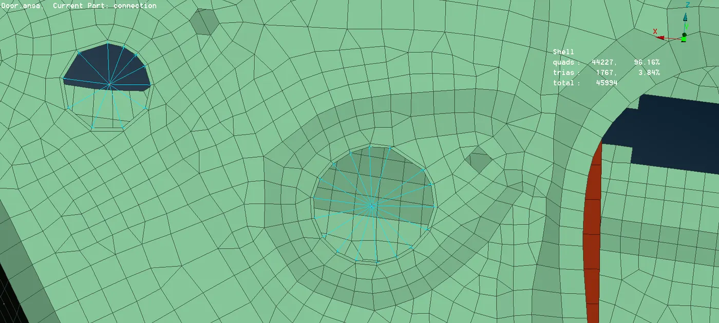
the only difference between them that is the first consists of the stem of the bolt connection but second is cluster type rigid connection.
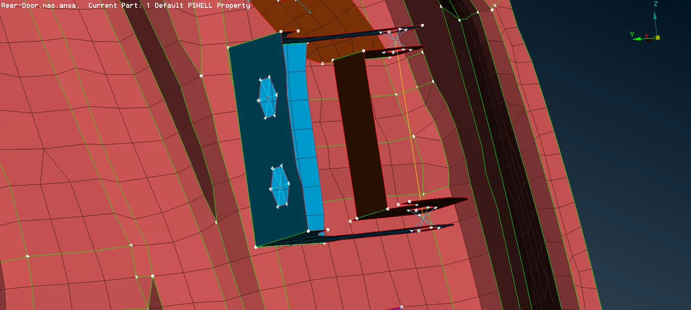
5. Door Hinged connection : The door hinged connection are created with RBE2 cluster element and in order to movement of rear door towards one direction delete the sixth degree of freedom under NASTRAN >> ELEMENTS >> INFO.
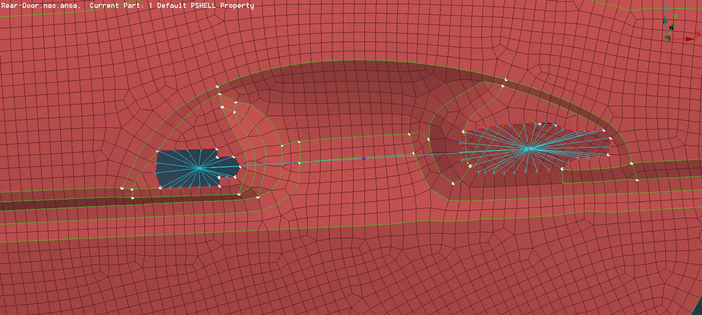
6. door handle connection : Handle connection is done by using the RBE2 elements along with the CONMI >> CONM2 >> NODES AT COG and apply mass to the centre of RBE2 .Mass is represented in tonns.
7. Spot weld connection : spot welding is a resistance welding process that is used primarily for welding two or more metal sheets together by applying pressure and heat to the weld area.
spot weld connections are used in point location and in door assembly there are so many parts where weld spot is needed.
First we have to create a 3D point by TOPO >> POINTS >> ON COG. Then convert the 3D pont into spot weld point.
now click on the connection and select the point by middle click connection manager box open. then adjacent component are selected and given with FE type as RB3-HEXA-RB3. in connection manager.
A PSOLID property is created and property id is entered in that connection manager list and then connection is realized.
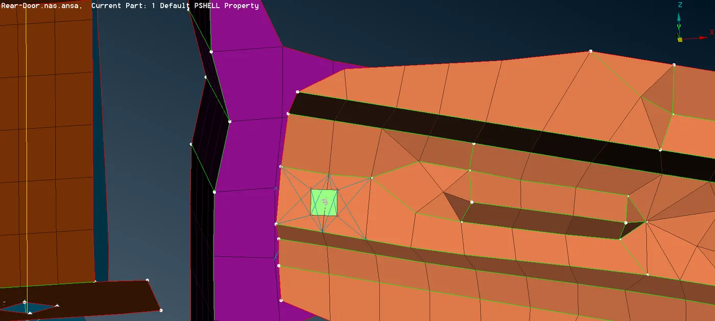
fig. Weld spot connection
8. Window glass connection : Glass is one which is movable assembly and the connection is done between the glass and weather beads. the connection is created by creating curve from the FE model by using the option FE2CURVE. Then the curve are converted into spotline by using convert option.
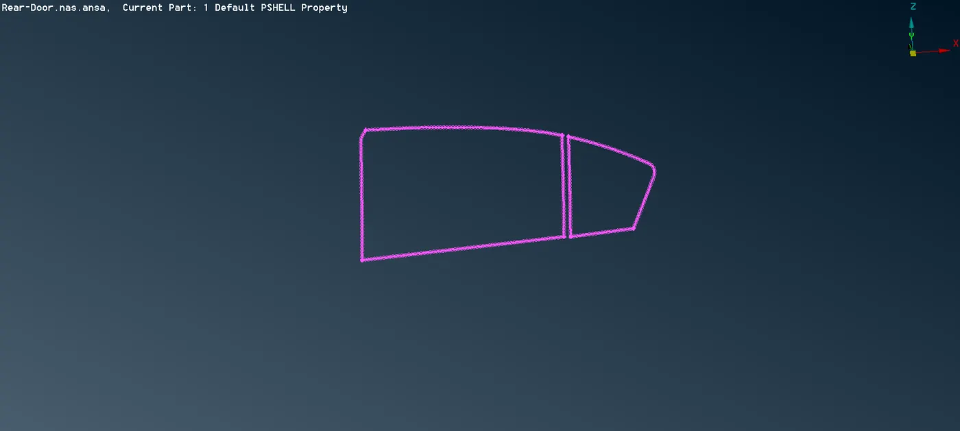
fig. Spot line for connection
then select the connection manager and select the spot line for making connection between glass and weather beads. the FE representative type is RBE3-CBUSH-RBE3 and then realized.
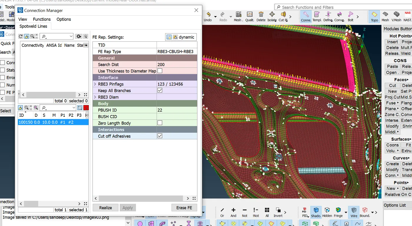
fig. CBUSH connection
It is found that CBUSH element are oriented in different direction. this lead to inappropriate assumption.in order to orient in global coordinates, all the CBUSH element are selected and modified by giving a value of 0 in CID tab. thus all the CBUSH element are globaly alligned towards one direction.
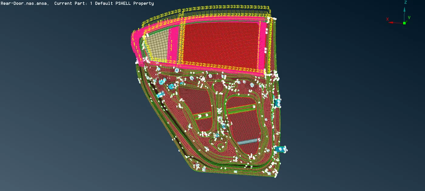
fig. CBUSH Element
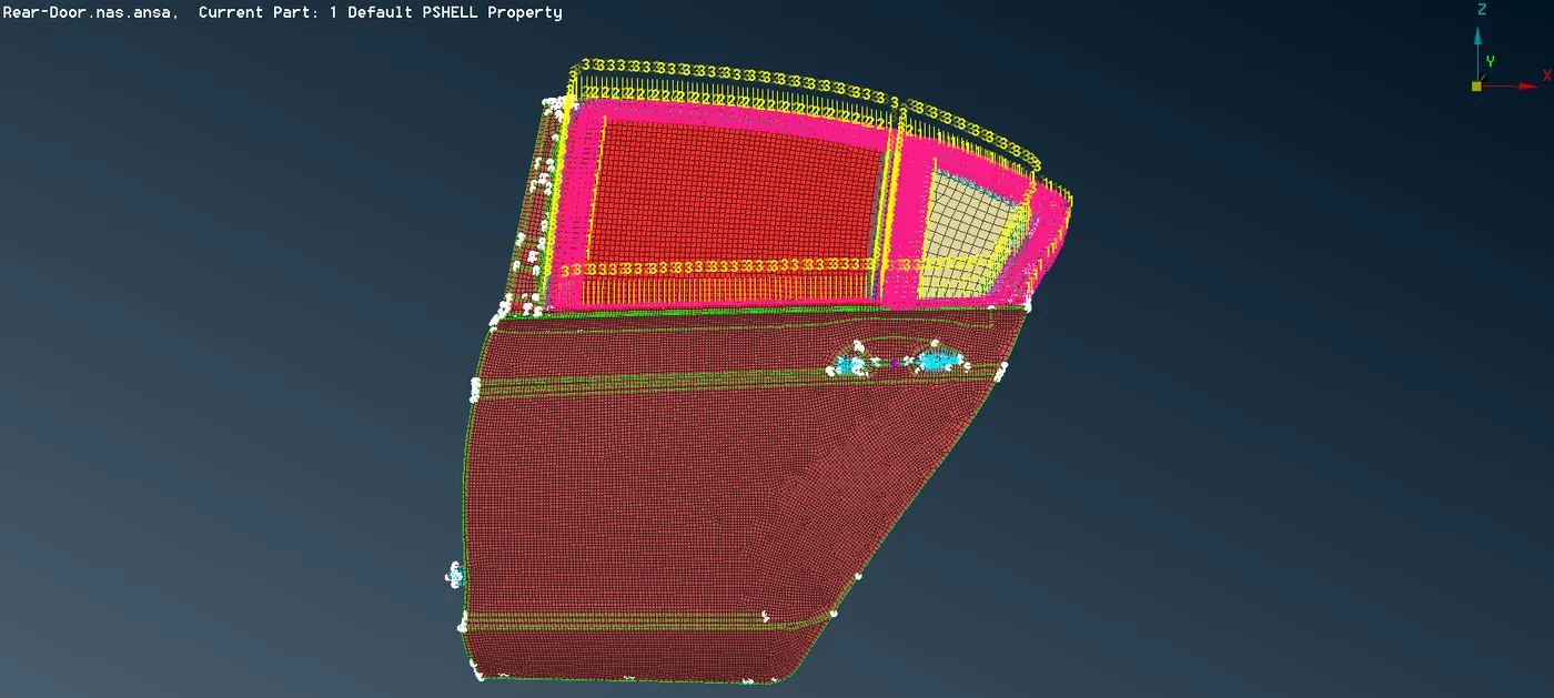
fig. Rear door connection
Conclusion : thus various connections are created and realized using different connection techniques for the rear door FE model using ansa.
Learning outcome :
- how to make Rigid and bolt connection.
- how to make spot weld connection.
- CBUSH element are realized and alligned.
- mass of handle is represented.