Week 9-Challenge
AIM :
Deploying the connection using Hyperworks
Objective :
Create the connectors and attach the different parts of the model
- Right_Rail_2 & Front_truss_1:- Seam-Quad(angled+capped+L)
- Left_Rail_2 & Front_truss_1:- Quad elements
- Front_truss_2, Front_truss_1 & Right_Rail_1:- Spot weld with 3 Layers and 5 mm Diameter
- Front_truss_2, Front_truss_1 & Left_Rail_1:- Hexa (Adhesive)
- Rear_truss_2 & Right_Rail_2:- Bolt Connector
Rear_truss_2 & Left_Rail_2:- Bolt Connector
- Right_Rail_1 & Right_Rail_2:- Spot-weld with Rigid Elements
Left_Rail_1 & Left_Rail_2:- Spot-weld with Spring Elements
- Rest all the component left Join them with suitable connectors
Introduction :
Connectors as the term said is used to connect the two or three components. They are geometric entities that are used to represent the CAD geometric connection in terms of FEA.
Now there are a number of connectors availabl;le in hyperworks but primarily connectors like spot, seam, bolt and adhesive or area are used.
Procedure :
Step1 : importing the model into hyperworks and performing the clean up
The current model is a frame assembly welding model that needs to be deployed with the required connection.
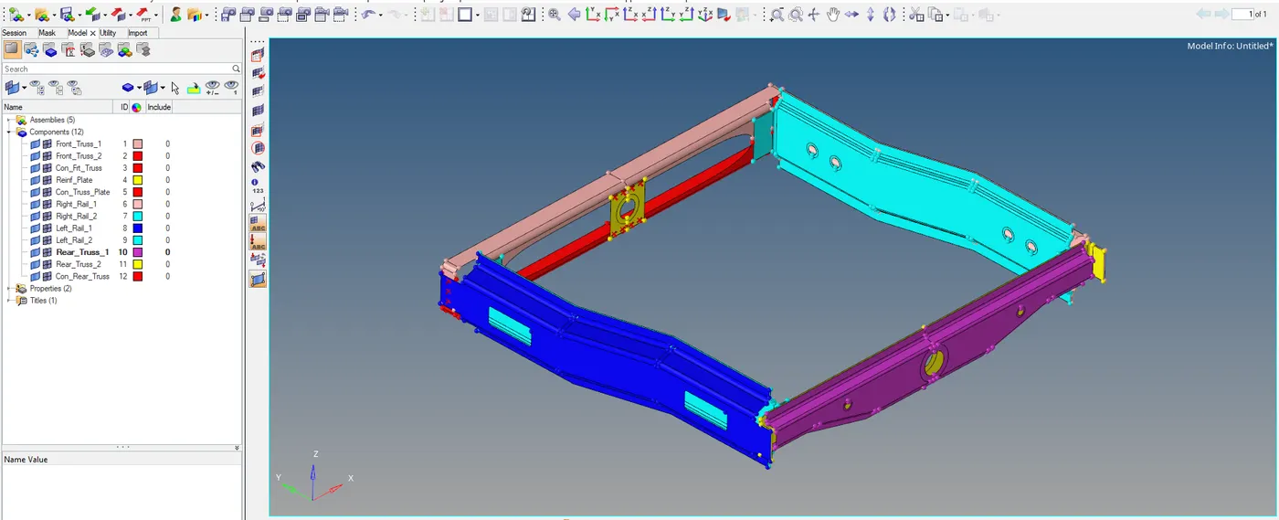
Fig- frame assemebly welding model
Clean up :
Before proceeding with the meshing of the assembly it needs to be reviewed and cleaned up.
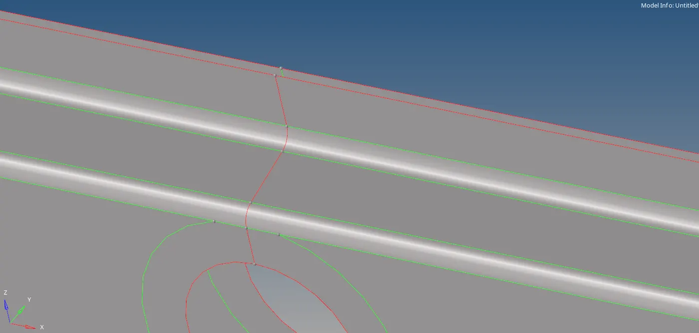
Fig- red lines indicating discontinuity
As seen from the above figure, the two lines need to be pasted to form the green line or the complete geometry. That can be done by using the toggle option under the quick edit tools .
 ]
]
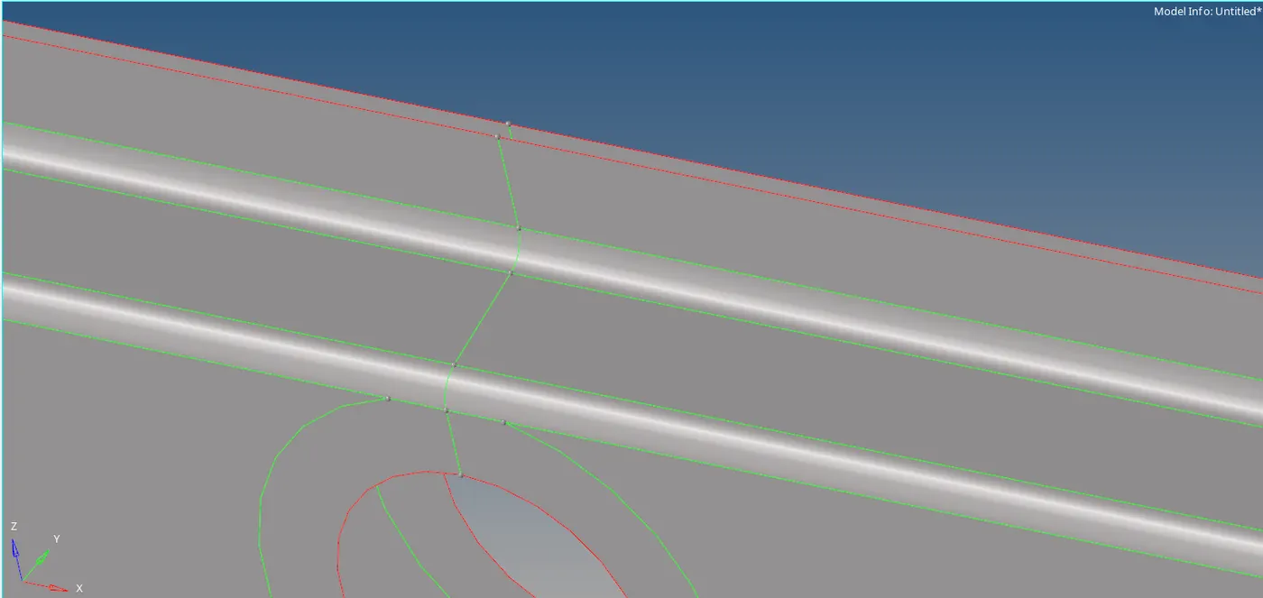
Fig - discontinuity fixed (green lines)
Step 2: Performing the 2D meshing
There are no quality criteria given so we will be taking the arbitrary values. Here we take the element size as 5 and perform the 2D meshing on the components given.
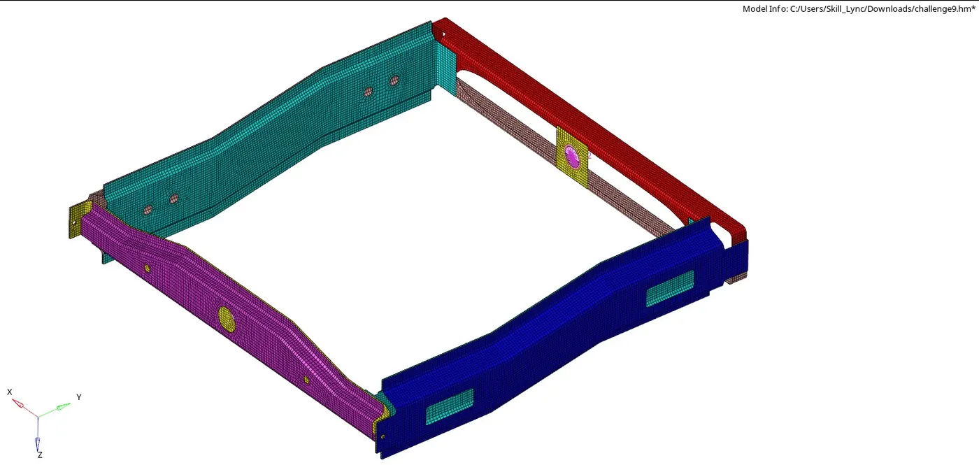
Fig- freme assembly meshed with elemnent size 5
Step 3 : Deploying the connectors
After the meshing is performed the connectors will be deployed at specified locations using the 2d connectors such as seam , spot and area.
1. Seam weld (angle-capped-l) connector
This connection needs to be deployed between the component right rail2 and front truss 1. The steps to followed as
- Switch on the right rail 2 and front truss 1 FEA only from the tab bar.
- Then go to the 2D > connectors > seam > select the seam quad (angle+CAPPED+L)

- Select the nodes and then select the components as the two components
- Spacing values will be elements size which is 5 and switch on the retain nodes
- Tolerance is the search distance between two components. Here its 5
- Then create the connection. If the connection is realized it will turn into green color other it will be red color or unrealized will turn yellow color.
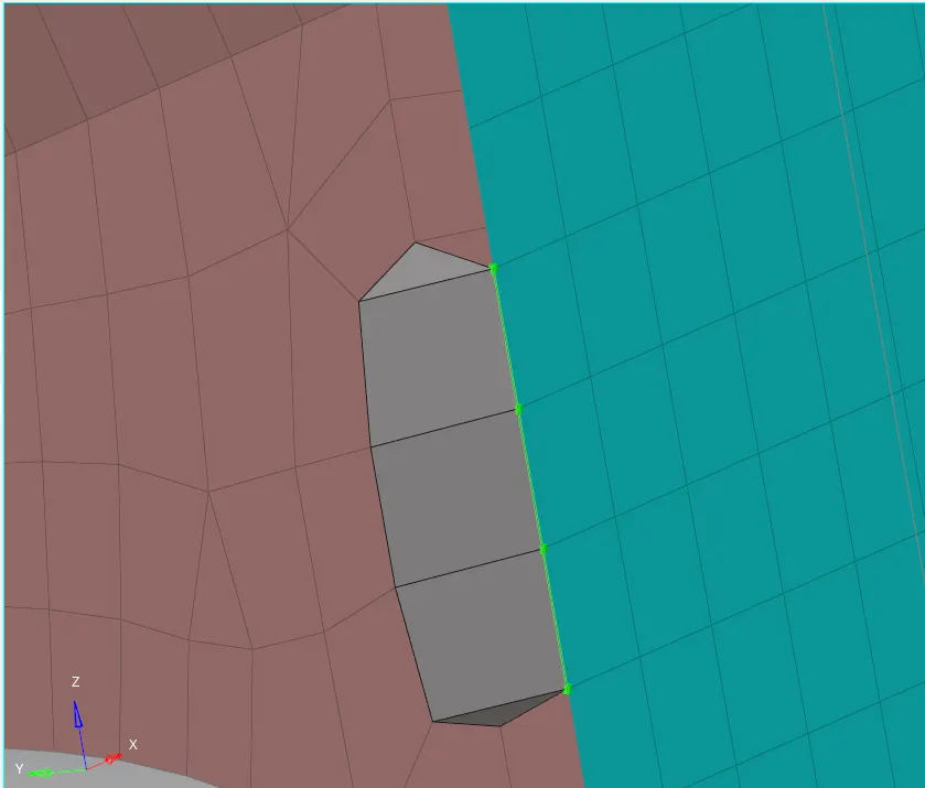
Fig- seam angle+capped+L connection
Note :
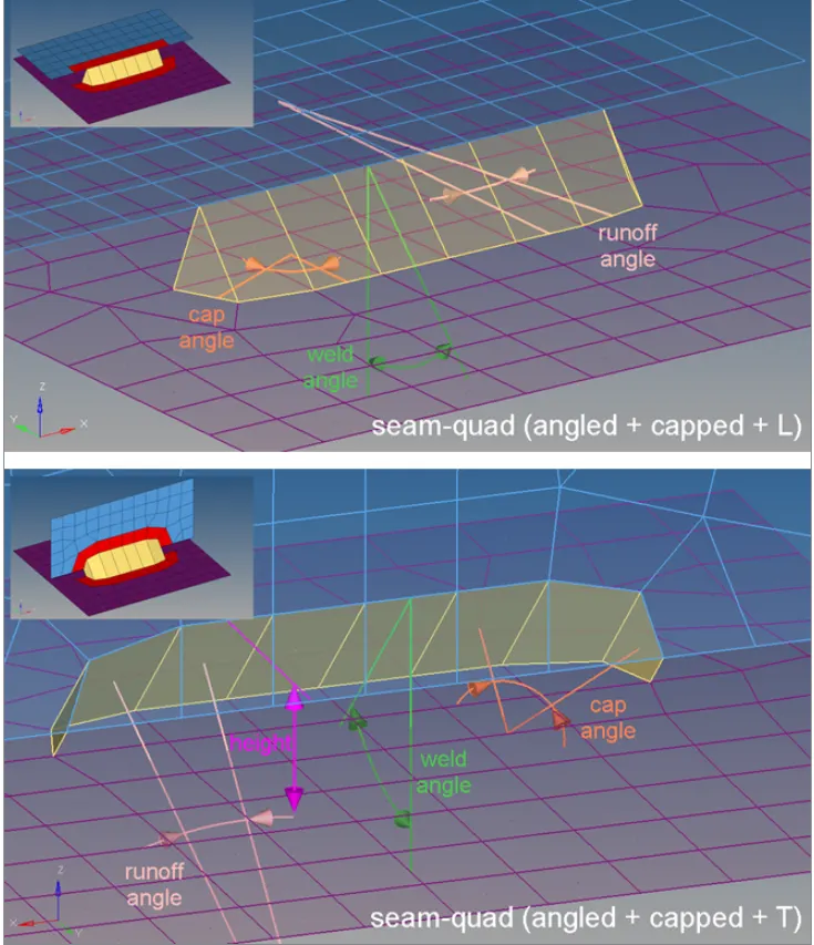
There are certain terminology related with the weld that are
Weld angle-the distance between the normal projection and the quad direction.
Principally it is allowed to define weld angles between 0.0 and 90.0. If the value is set to 0.0 an internal thickness-based calculation is used. If the value is set to 0.0 and no thickness is defined the connector will fail.
If the angle is created in the wrong direction, the seam can be reverted by enabling the reverse direction checkbox and performing a derealization.
Cap angle-Depending on the seam-quad type, the cap angle is measured differently.
Measured between the normals of the cap element and the second-to-last element of the seam.
Measured between the edge normals of the cap element and the second-to-last element of the seam in the plane of the opposite link.
Height-the distance between the projection point and the start-point of the angled quads.
Only available for T-seams.
The height needs to be chosen in an extent to bridge the gap between the links. Also, the height strongly influences the quad length, especially in cases of very large weld.
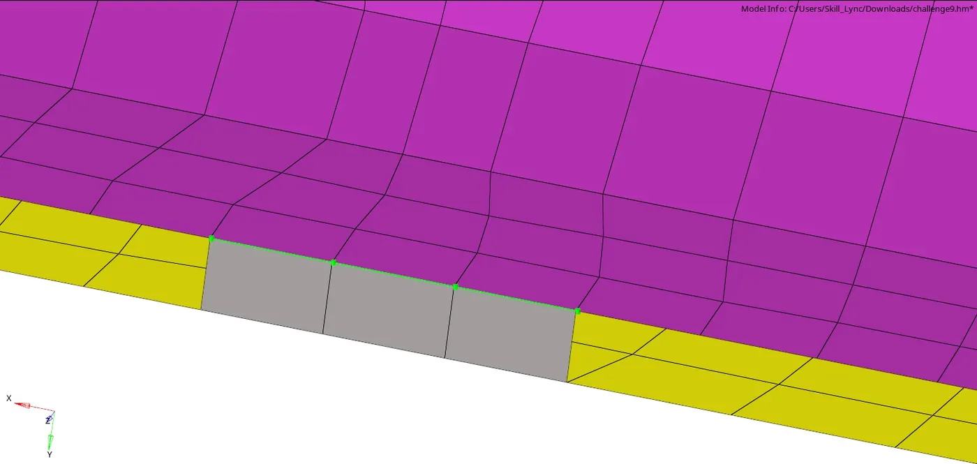
2. Quad elements :
This connection will be deployed between the left rail 2 and front russ 1. Quad connectors fall under the seam connectors only. The steps are same as the above only
- Select the nodes from one component
- Select the components as two left rail2 and front truss 1
- Tolerance and spacing will be same as earlier and then create

- The quad imprint is kept only because we have the existing elements that need to connect otherwise if the imprint is turned off duplicate elements are created .
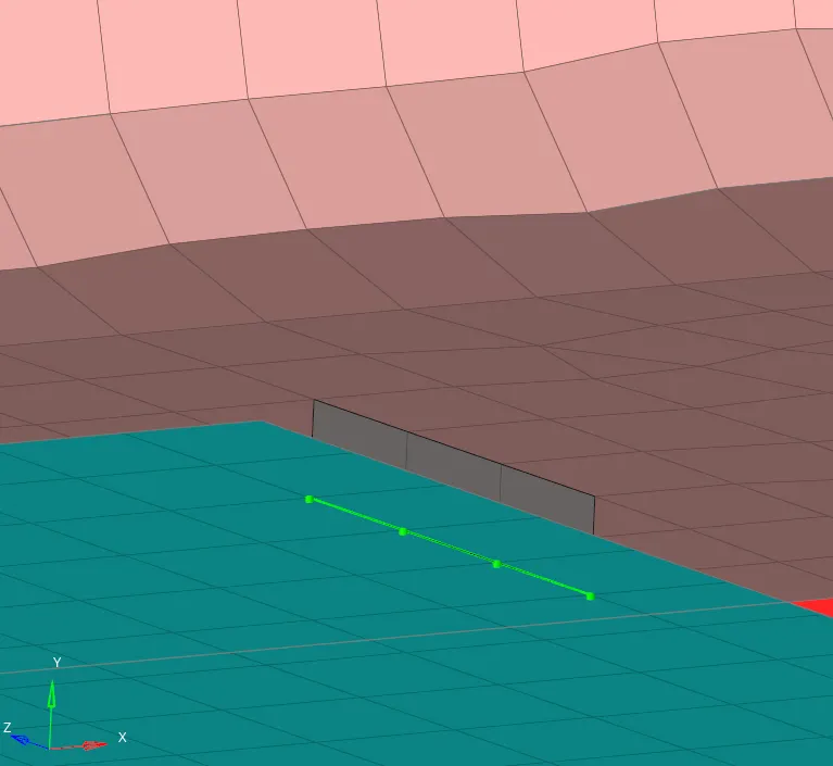 ]fig - seam qaud connection
3.Spot weld
Here the spot weld is used to connect three components as front truss 1,2 and right rail 1. Steps to deploy spot connection are as followed
- Switch on only 3 required components from the tab bar
- Go to 2D>connectors >spot
- Select the type as weld
- Select the nodes from the any top component and the components as all three components

- The number of layers are put three because the components here 3 only
- Diameter as 5 and the rest of the option as mesh dependent and project and find nodes are kept as it is only.
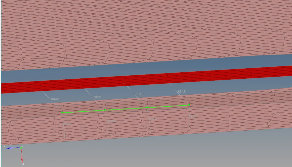
Fig- spot weld
4. Hexa adhesive
This connection falls under the seam connectors only. Here its deployed between three components as front truss 1,2 and the left rail1. Steps to deployed as follows
- The components that are required are only switched on
- Go to 2D>connectors >seam > type as hexa adhesive
- Select the node list from one component and then select the comp as two components
- Spacing and tolerance are kept as 5 .
- Coats and strips are kepts as1 as there is significantly small spacing between two components the elements will fail in that connector.
- We can chose the midpoint or positive or negative direction to obtain the connection
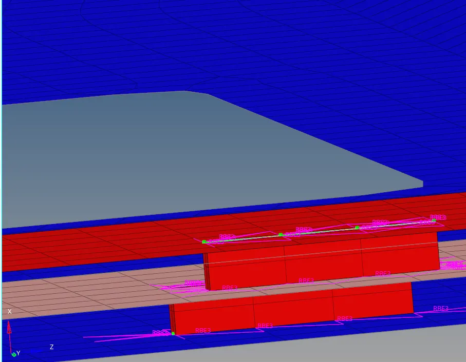
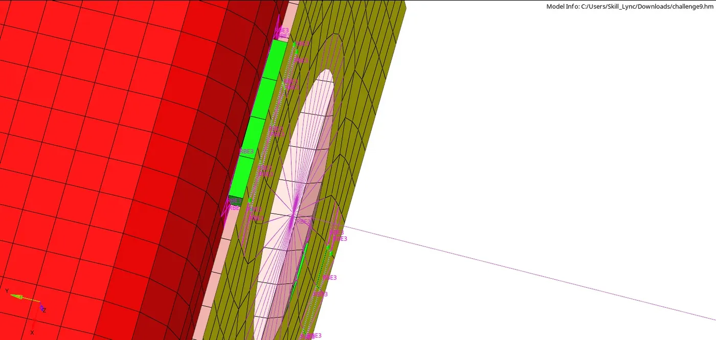
Fig- seam hexa adhesive
Note :
The hexa connection is developed as a rbe3 connection. The difference between the RBE2 and RBE3 is that RBE2 is considered to be infinitely rigid while RBE3 are considered to be a a little stiffer.
5. Bolt connector
The bolt connection is also a RBE2 based connection since they are considered to be rigid and they are not used as a component for study. Here we have to deploy the 2 bolt connection
Rear truss 2 and right rail2
Rear truss 2 and left rail 2
The steps are as follows
- Switch on the required component for the bolt connection
- Go to 2D>connectors > bolt

- Select any one node under the node
- Select component as two components
- Layer as 2 since only two components are present
- Tolerance as 5
- Type of the bolt as general
- Now select the create hole , if none since here there are holes present and create
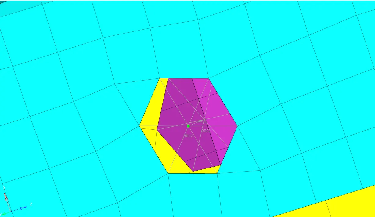
Fig- Bolt connection
6. Spot weld with rigids and springs
All the steps for the spot weld are followed as mentioned above but the type is selected is rigids and springs respectively
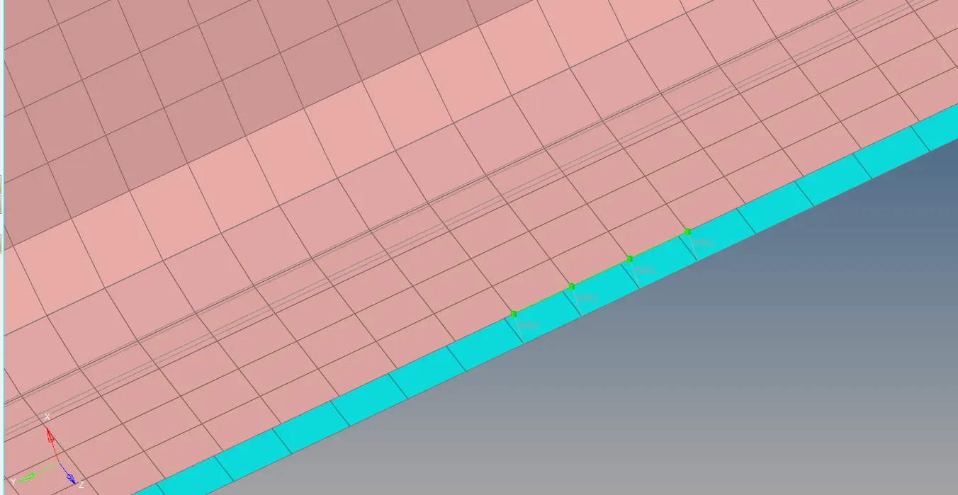
Fig- spot rigid
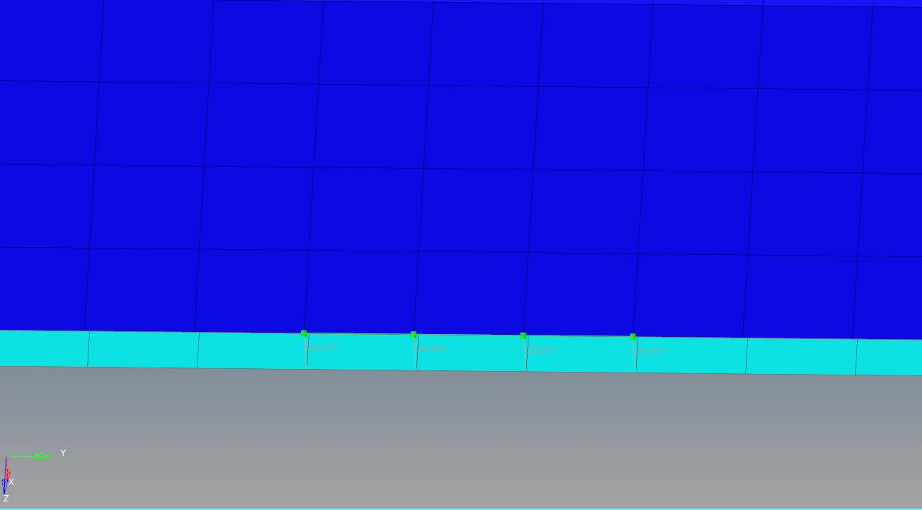
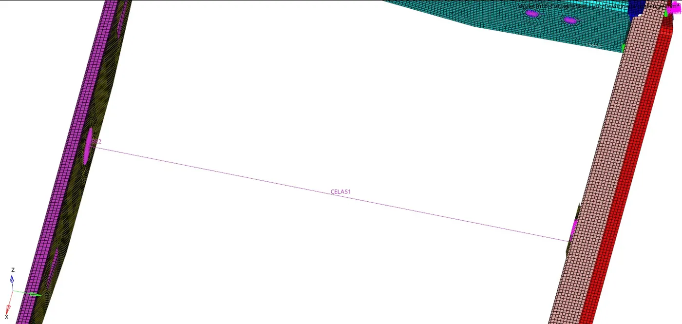
Fig- spot spring
The only difference between the rigids and spring is the elements type is represented as rbe2 and celas1 .
8. Miscellaneous connection
Area adhesive
Seam angled
Rbe 2 spring
Results :
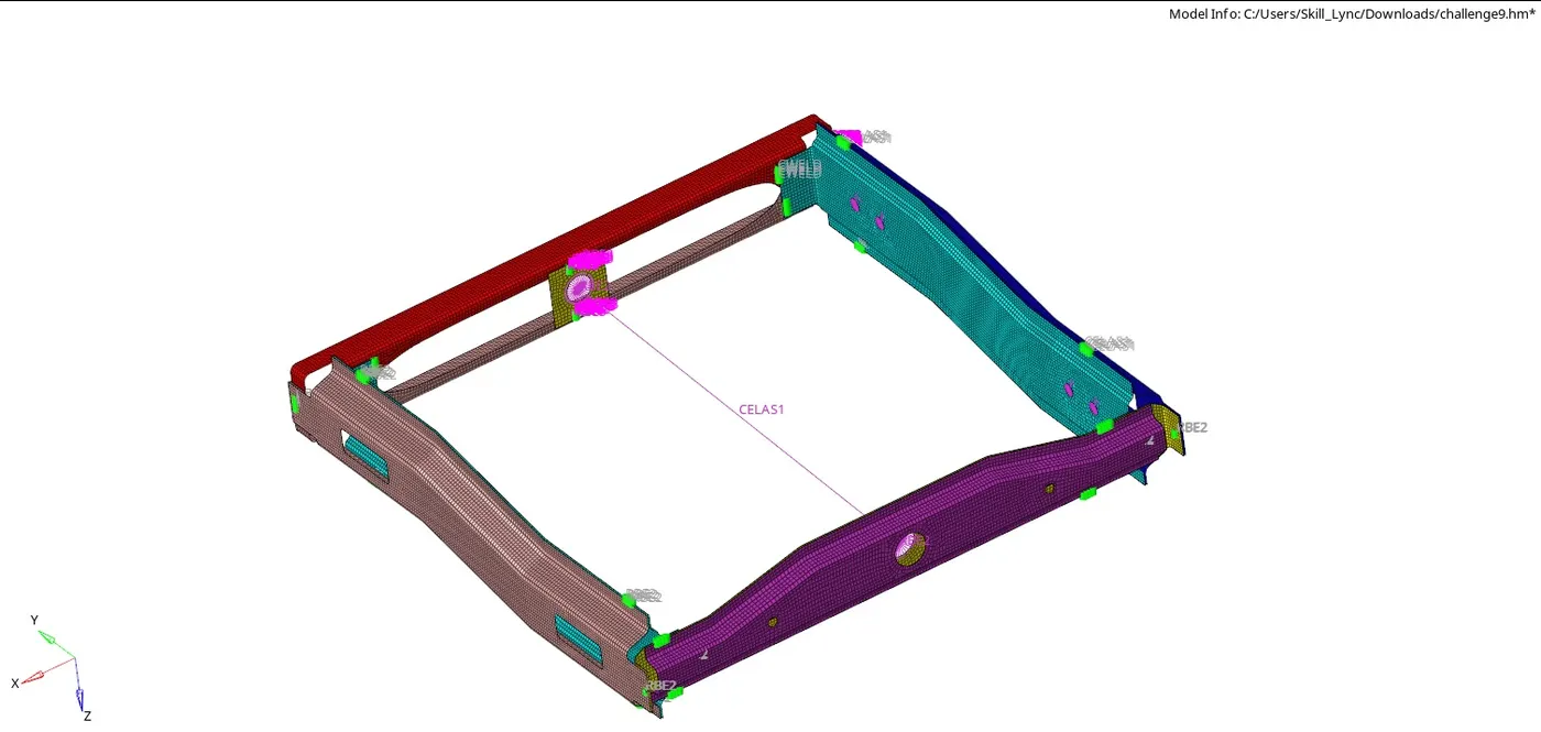
fig- final frame assembly with deployed connectors
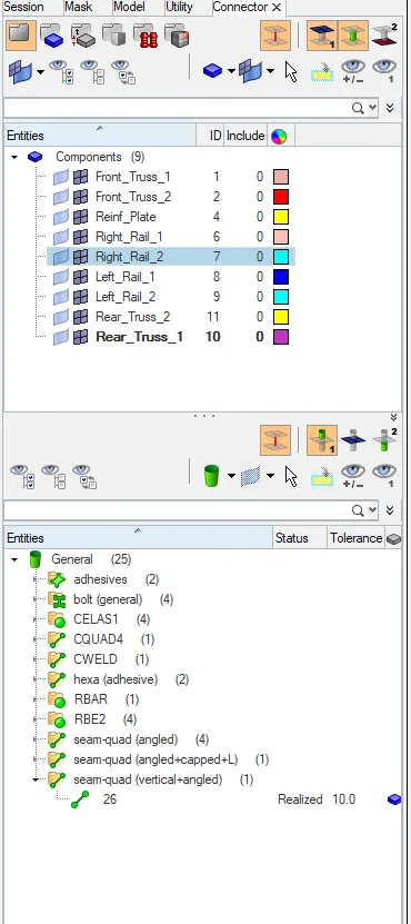
Fig-connector window
Conclusion:
All the required connection were made in the frame assembly welding model successfully.
link for the model : https://drive.google.com/drive/folders/1sgvmdhCBngifhOzVWQNnOqj-5s6Kp1mb?usp=sharing
refrences : https://skill-lync.com/knowledgebase/realizing-connectors