Week 9-Challenge
Objective - To create connectors and attaching various parts of the given frame assembly model.
procedure -
- In the first step imported the given .hm file in the hypermesh window.
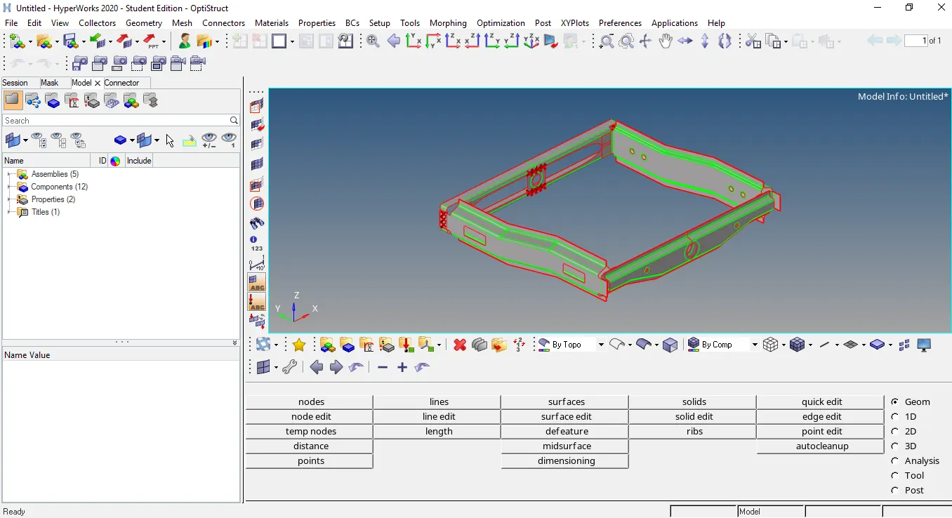
picture representing the imported frame assembly .hm file in hypermesh
- In the next step meshed all the components of the given frame assembly by clicking the shortcut key F12 automesh panel opens and meshed all these components one by one. Also to get the better mesh remeshed the mesh again and again until a good mesh is created. As to connect the components it is inevitable that mesh should be of good quality so that connectors can be created and realsied easily.
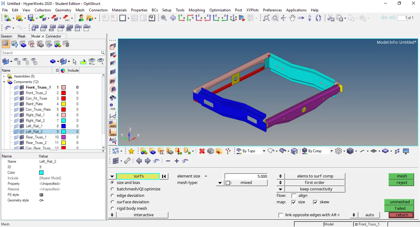
picture representing the meshing of all components which further remeshed to get the better mesh.
picture representing the tree area to assign the property and material to the elements
- In the next step hided all the components of the given assembly model except Right_Rail_2 & Front_Truss_1. Then under the 2D panel under connectors option where under the seam connectors option selected the seam quad(angled+capped+L) connector and connected these two components.After creating connector the mesh of both the components distorted and rectified by using the remesh option.
picture representing the connector Seam-Quad(angled+capped+L) between the components Right_Rail_2 & Front_truss_1.
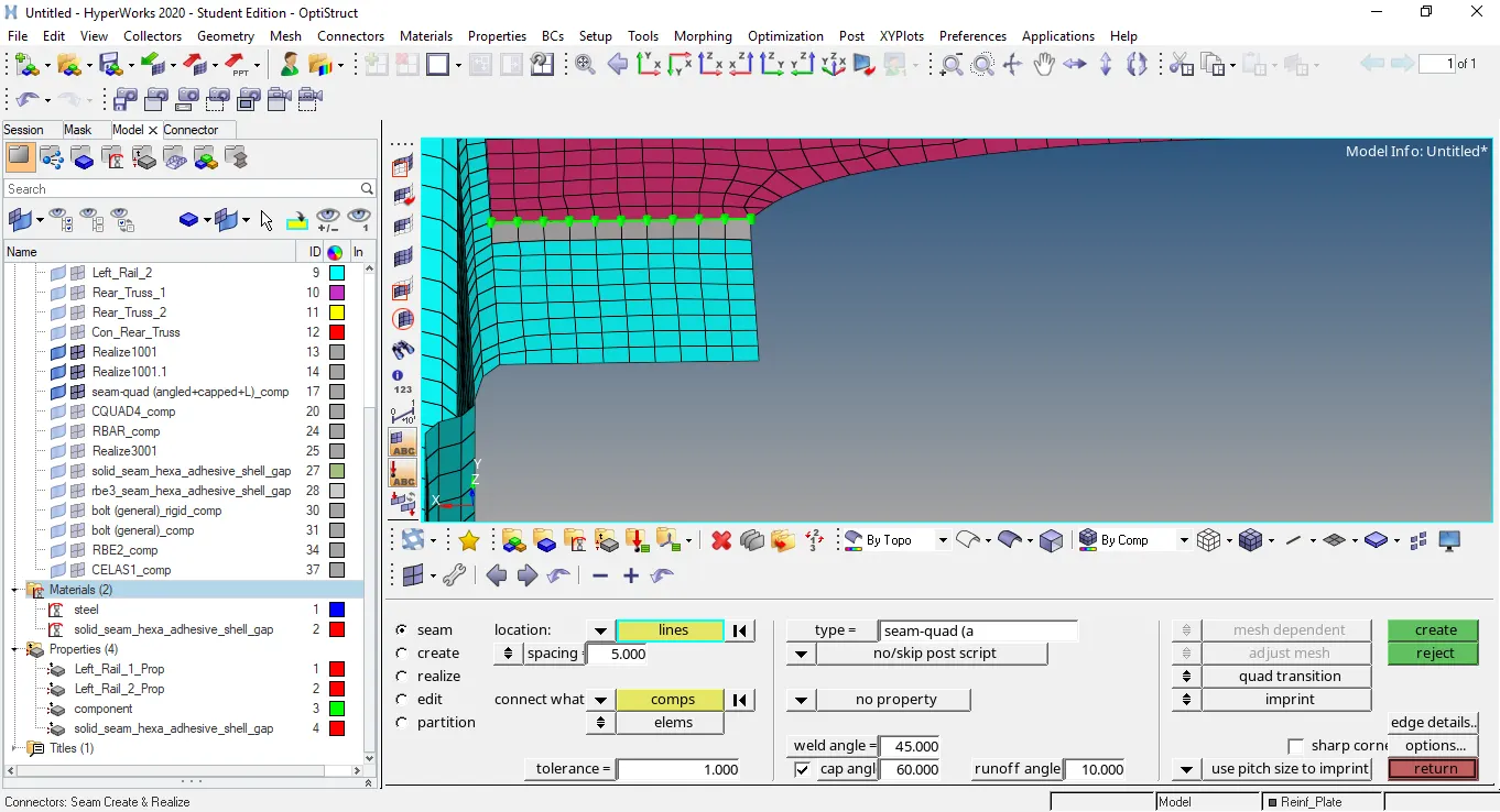
- In the next step hided all the components except the Left_Rail_2 & Front_truss_1.These two components are connected by using the connectors as seam quad under the connector panel.The mesh of both the components distorted after creating connector and rectified later by doing remesh.
 picture representing the components Left_Rail_2 & Front_truss_1 connected by using the connector seam quad.
- In the next step connected the components Front_truss_2, Front_truss_1 & Right_Rail_1 by using the connector Spot weld with 3 Layers and 5 mm Diameter.All these three components are connected in one step and mesh of these components remains undistorted after creating these connectors.
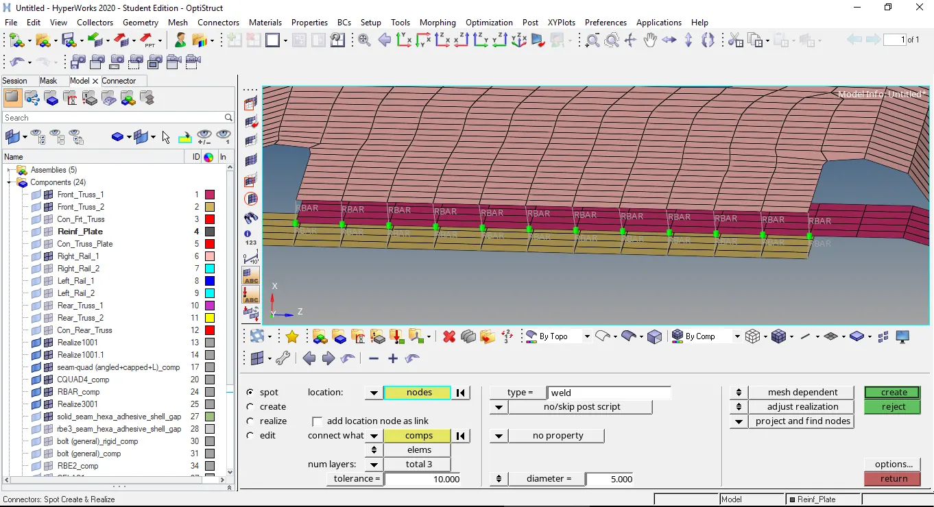
picture representing the components Front_truss_2, Front_truss_1 & Right_Rail_1 by using the connector Spot weld with 3 Layers and 5 mm Diameter.
- In the next step components Front_truss_2, Front_truss_1 & Left_Rail_1 are connected by using the Hexa (Adhesive) connector.These three components are connected in two steps by selecting the two components in each step.After creating connector the mesh remains same.This connector is present under the seam connector.
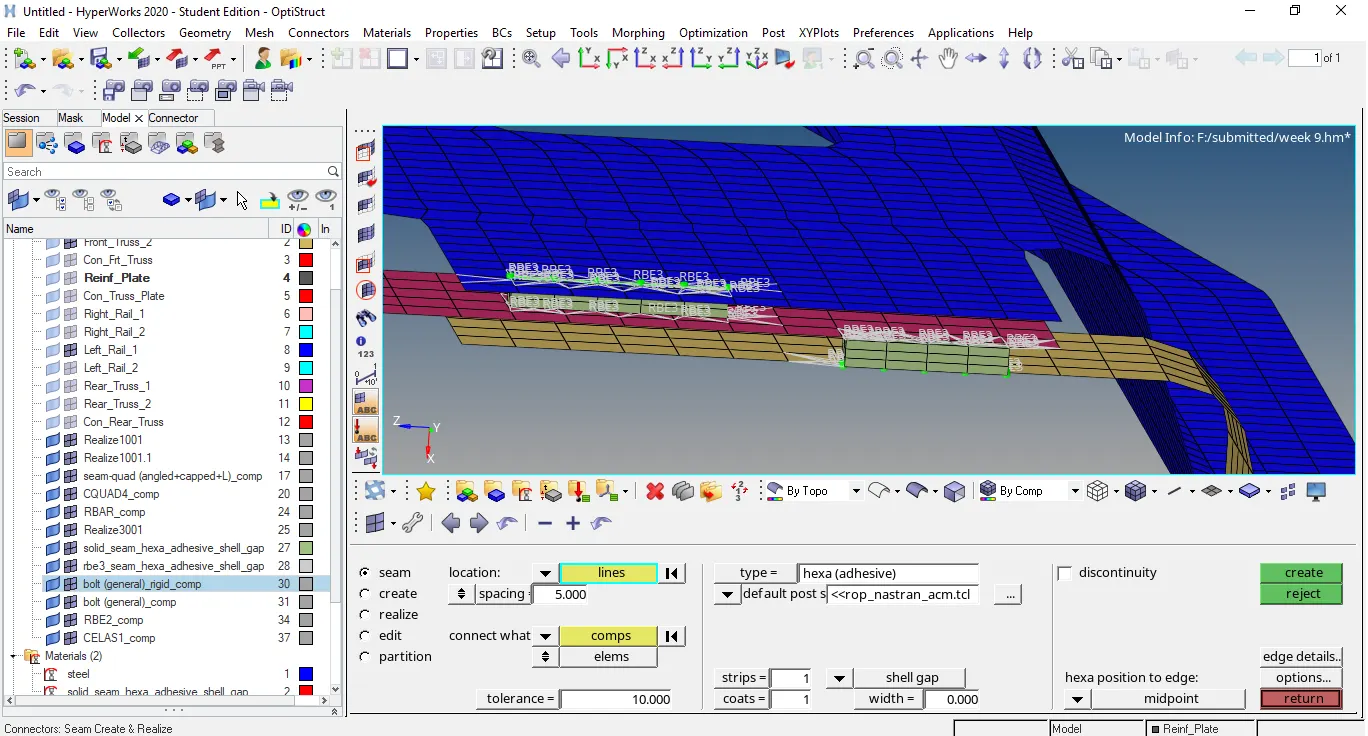
picture representing the connector Hexa (Adhesive) to connect the components Front_truss_2, Front_truss_1 & Left_Rail_1 under seam connector option.
- In the next step components Rear_truss_2 & Right_Rail_2 are connected by using the bolt connector under the connector panel.In this after creating the bolt connector as general bolt the mesh of both the components get distorted and by doing remeshing it is rectified.
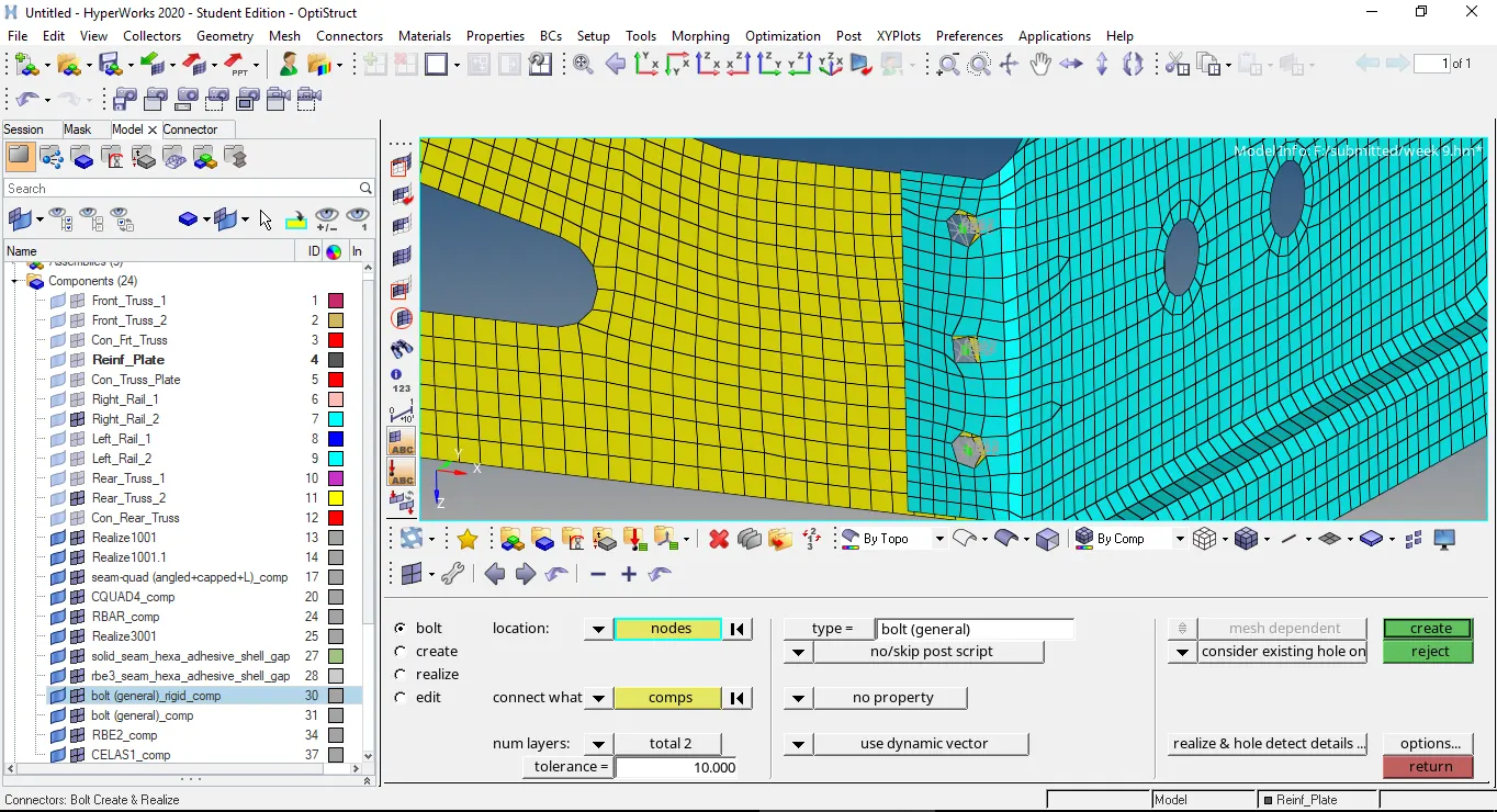
picture representing the bolt connector to connect the Rear_truss_2 & Right_Rail_2 components.
- In the next step components Rear_truss_2 & Left_Rail_2 are connected by using the Bolt connector and mesh is rectified after creating bolt connector.
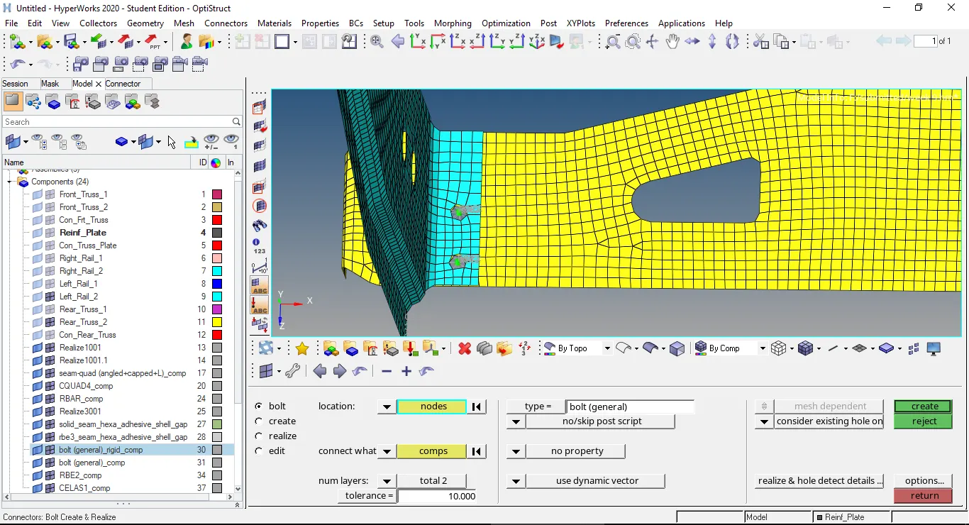
picture representing the bolt connector between the Rear_truss_2 & Left_Rail_2 components.
- In the next step the components Right_Rail_1 & Right_Rail_2 connected by using the Spot-weld with Rigid Elements.Rigid elements are selected under the spot connector option and mesh remains same after creating these connectors.
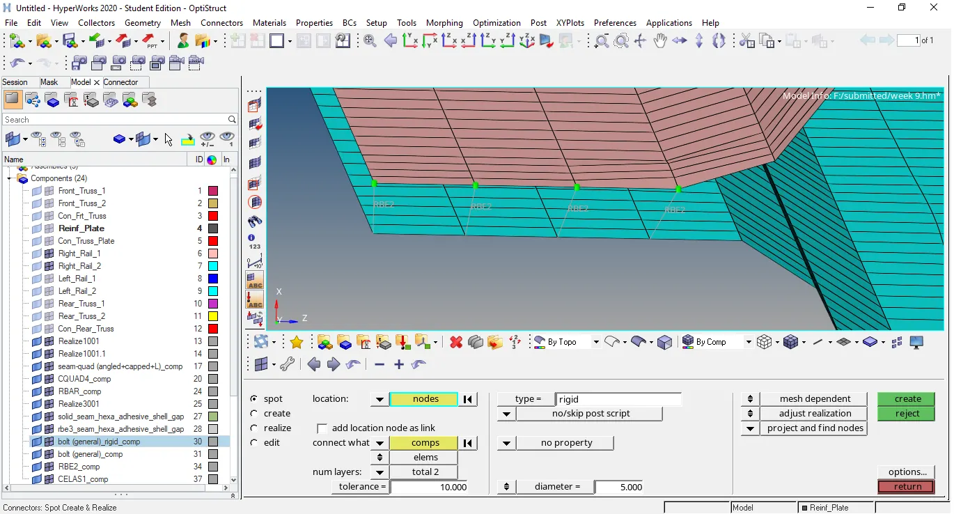
picture representing the rigid elements under the spot weld connector option and the components Right_Rail_1 & Right_Rail_2 are connected by using these connectors.
- In the next step connectors spot-weld with spring elements are used to connect the components Left_Rail_1 & Left_Rail_2.
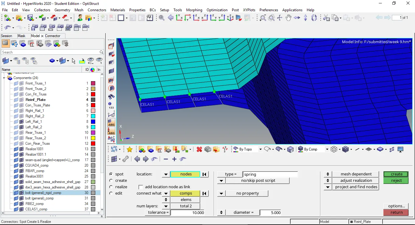
picture representing the components Left_Rail_1 & Left_Rail_2 are connected by using the connector spot-weld with spring elements.
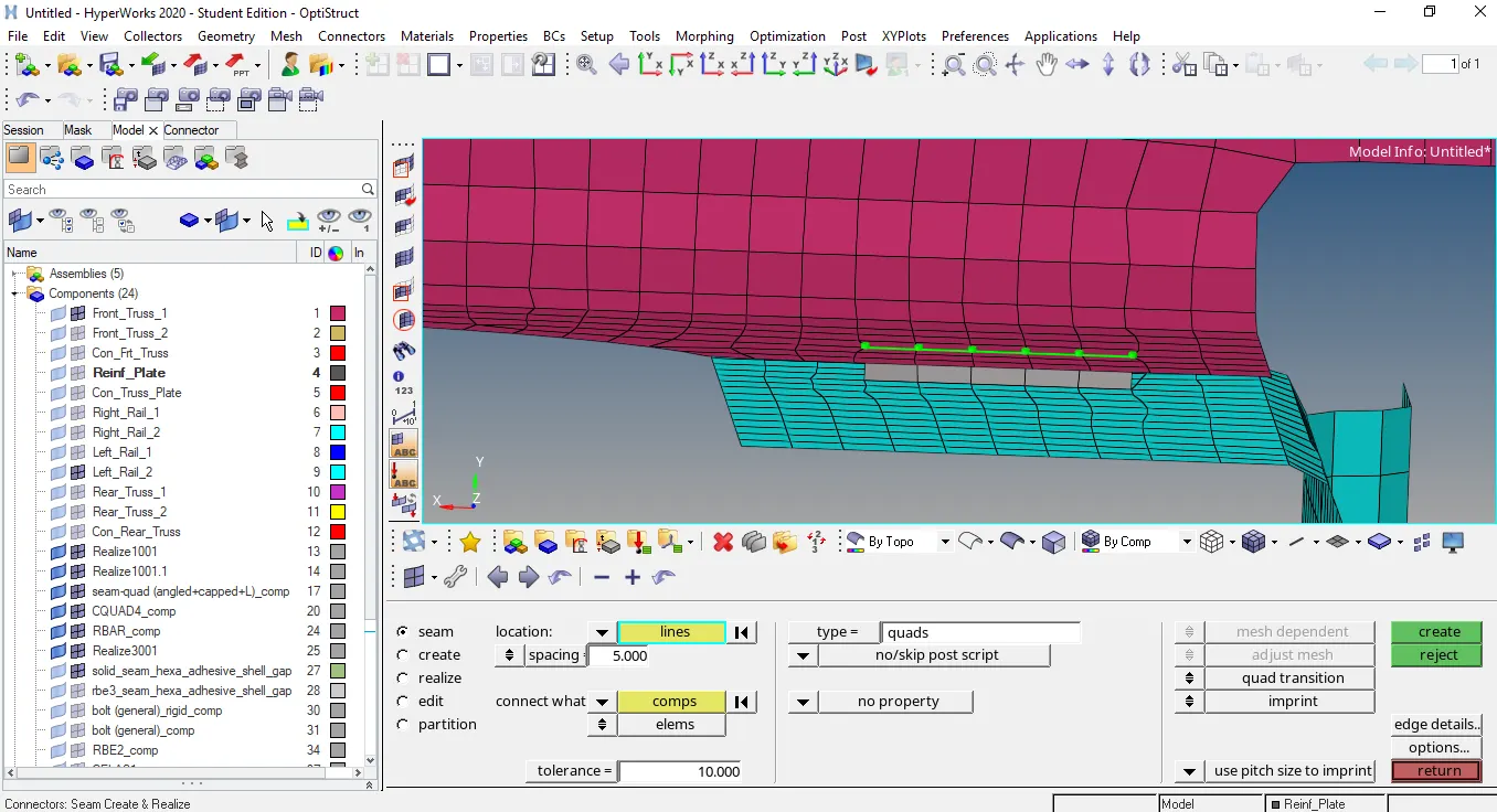
- In the next step components Reinf_plate and Front_truss_2 are connected by using the weld connector abd components Reinf_plate and Front_truss_1 are connected by using the weld element under seam connector panel.
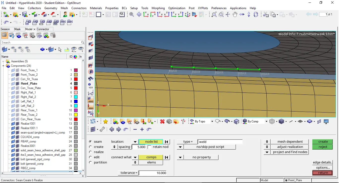
picture representing the components Reinf_plate and Front_truss_2 are connected by using the weld element under seam connector option.
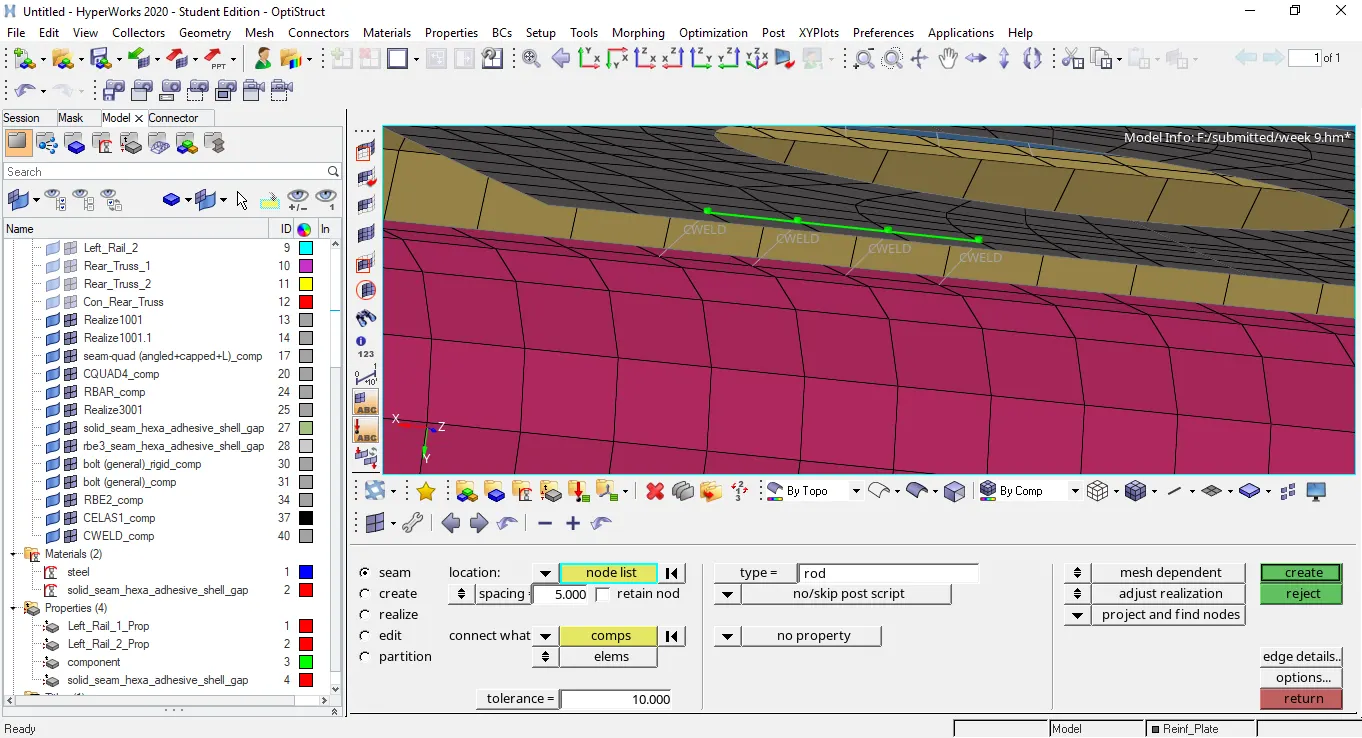
picture representing the components Reinf_plate and Front_truss_1 are connected by using the rod elements.
- In the next step components left_rail_2 & Rear_Truss_1 are connected by using the hemmings under the area connector option.
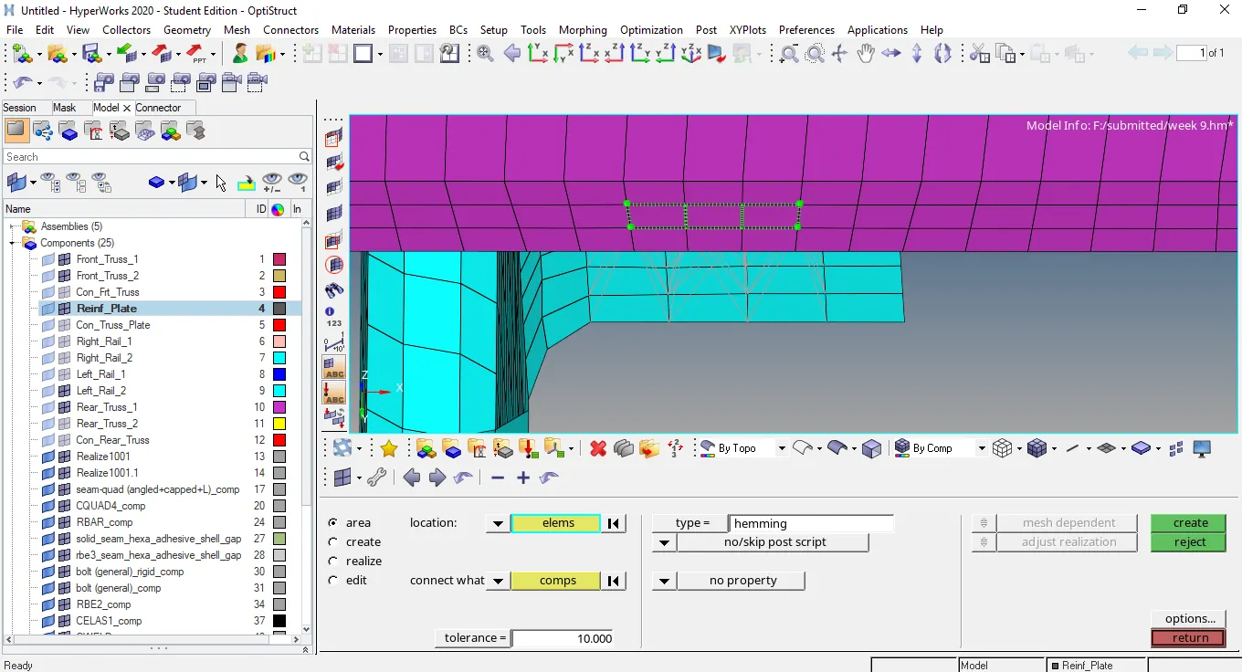
picture representing the components left_rail_2 & Rear_Truss_1 are connected by using the hemmings under the area connector option.
- In the next step components Rear_Truss_1 & Rear_Truss_2 are connected by using the adhesives under area connectors.
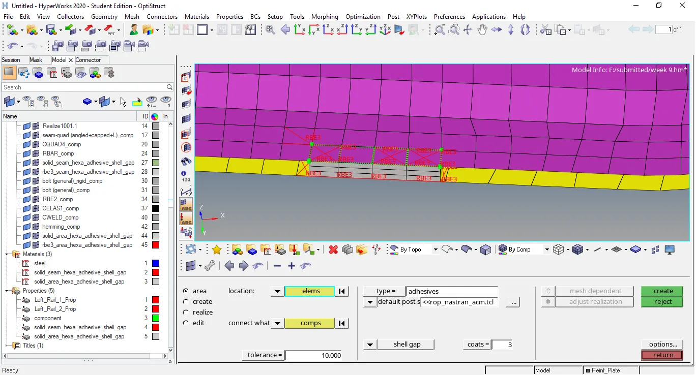
picture representing the components Rear_Truss_1 & Rear_Truss_2 are connected by using the adhesives under area connector.
- In the next step components Left_Rail_1 & Rear_Truss_2 are connected by using the penta(mig+L) seam connector.
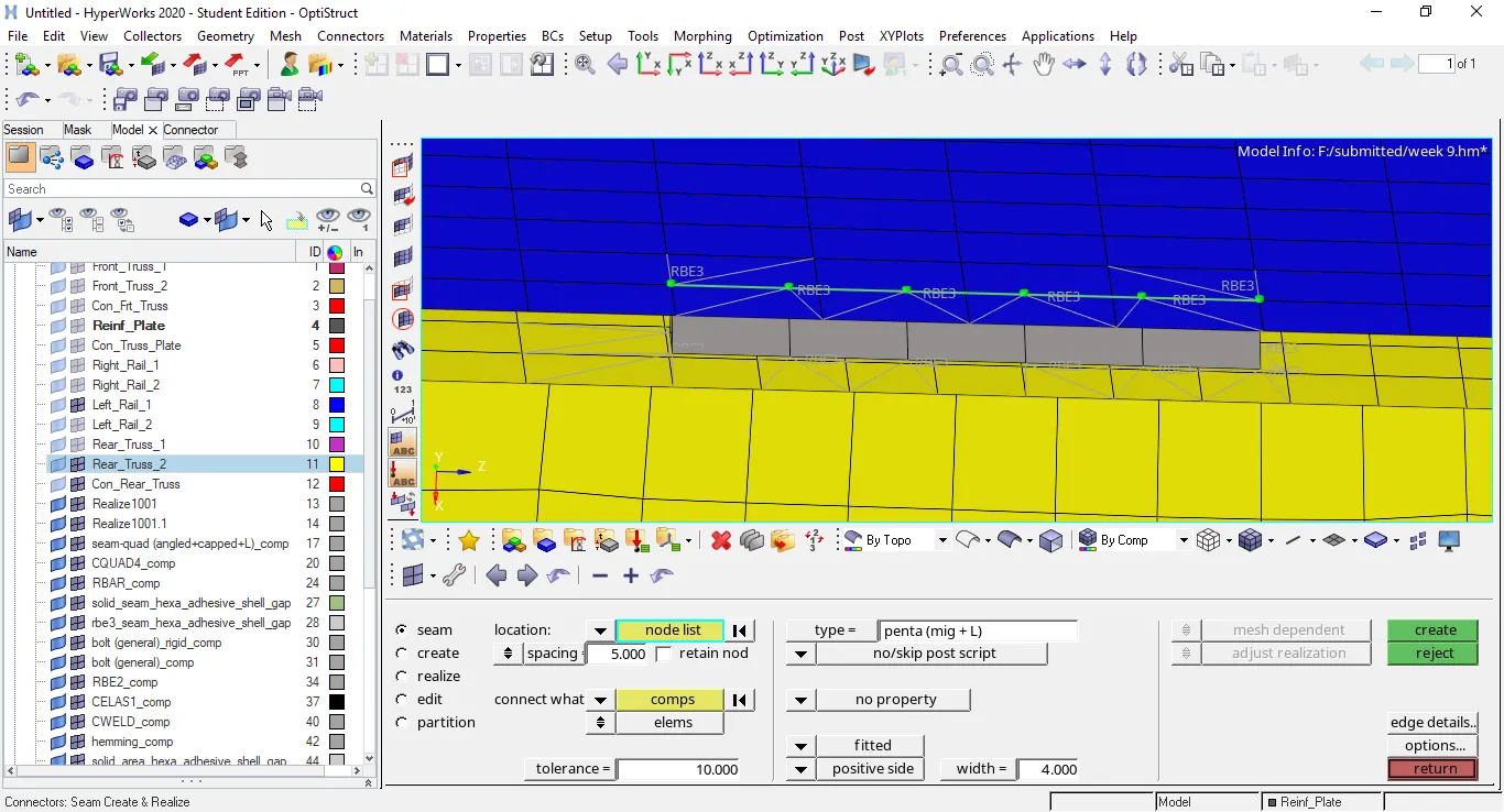
picture representing the components Left_Rail_1 & Rear_Truss_2 are connected by using the penta(mig+L) seam connector.
- In the next step components Right_rail_1 & Rear_Truss_2 are connected with gap elements under the spot connector option.
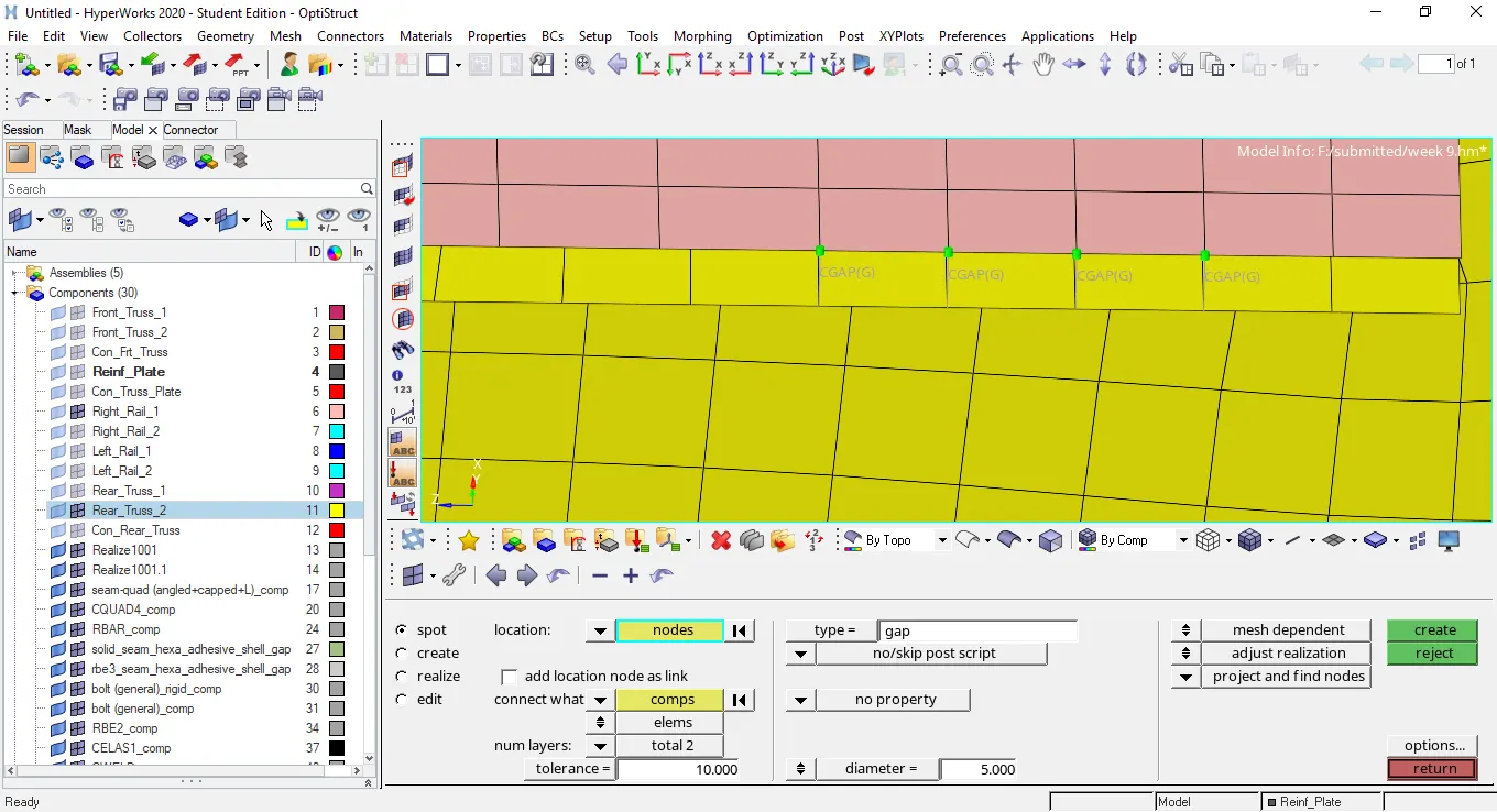
picture representing the components Right_rail_1 & Rear_Truss_2 are connected with the gap elements under the spot connector option.
- In the next step components Left_Rail_2 & Front_Truss_2 are connected with the hexa adhesive under the seam connector option.
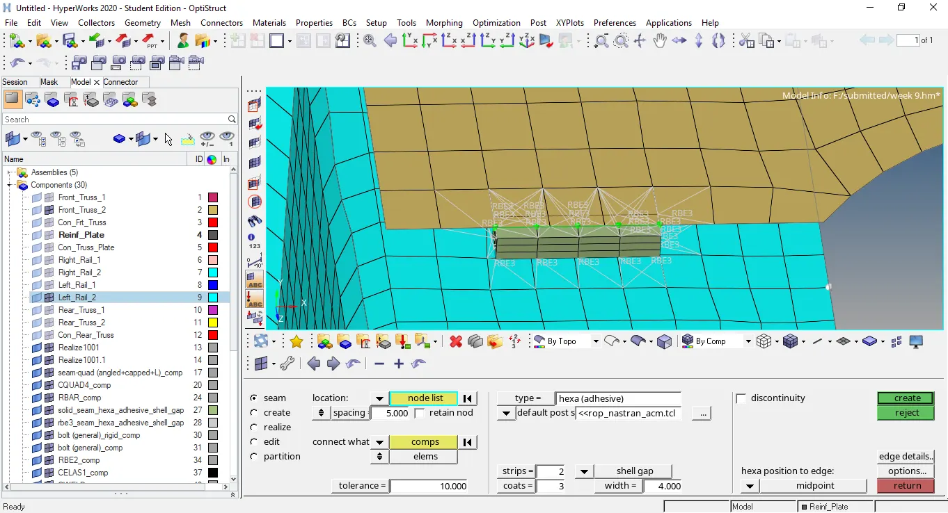
picture representing the components Left_Rail_2 & Front_Truss_2 are connected with the hexa adhesive under the seam connector option.
conclusion - connectors are used to connect the different components of the assembly.
connectors are available under the 1d,2d and 3d page.
All connectors are 1d in nature though some connector like hexa adhesives etc looks in 3d form but are the 1d in nature.
To connect the 2d meshed components 2d connectors are used.
To connect the one 2D meshed and other 3D meshed component 3D connectors are used.
Each connector has different property and is used specifically at the specific positions.
All the components of this frame are connected holistically by using the 2D connectors.