Creating connectors in hypermesh
OBJECTIVE: To attach various parts of the model by creating the connector mentioned in the challenge.
Various parts of the model along with its attaching connector is mentioned below:
- Right_Rail_2 & Front_truss_1:- Seam-Quad (angled+capped+L)
- Left_Rail_2 & Front_truss_1:- Quad elements
- Front_truss_2, Front_truss_1 & Right_Rail_1:- Spot weldwith 3 Layers and 5 mm Diameter
- Front_truss_2, Front_truss_1 & Left_Rail_1:- Hexa (Adhesive)
- Rear_truss_2 & Right_Rail_2:- Bolt Connector
- Rear_truss_2 & Left_Rail_2:- Bolt Connector
- Right_Rail_1 & Right_Rail_2:- Spot-weld with Rigid Elements
- Left_Rail_1 & Left_Rail_2:- Spot-weld withSpring Elements
- Rest all the component left, Join them with suitable connectors
PROCEDURE:
STEP 1: Import the model into the hypermesh and clean the geometry.
STEP 2: Delete the solids (If any) from the model by selecting delete > solids > delete entity.
STEP 3: Mesh the geometry using automesh option from 2D panel.
STEP 4: After completing 2D meshing, model should be cleared with the elemental error.
Now after this, we are going to attach various parts of the model with appropriate connectors and the procedure for which is mentioned below:
PART-1 : Right_Rail_2 & Front_truss_1:- Seam-Quad(angled+capped+L)
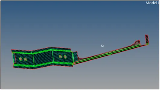
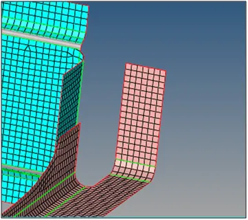
The former image shows the Right rail 2 and front truss 1 parts of the model and the later image shows the area where the connector needs to be created in order to attach both parts.
STEP 1: Select 1D/2D > connector > Seam option.
STEP 2: Now select the location where the connector needs to be created by clicking ‘node list’.
STEP 3: Tick the checkbox of ‘retain nodes’ option to retain the position of nodes, while creating and realizing a connector.
STEP 4: Specify the spacing value as 5 (Since element size = 5) and select the ‘comps’ option under ‘connect what’ in order to create the connector between those two component.
STEP 5: Specify the tolerance value based on the distance between the two components. In this case its 4.
STEP 6: Select the type as ‘Seam-quad (angle +capped + L)’.
STEP 7: Click on create button to create the seam quad connector.
STEP 8: Sometimes mesh is altered while creating the connectors. If this happens, then fixed then altered mesh by remeshing those elements or by other ways.
The component will be connected as shown below:
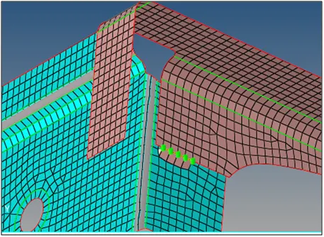
PART-2 : Left_Rail_2 & Front_truss_1:- Quad elements
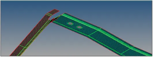
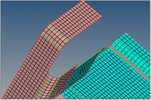
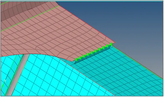
The former image shows the Left rail 2 and front truss 1 parts of the model and the later image shows the area where the connector needs to be created in order to attach both parts.
STEP 1: Select 1D/2D > connector > Seam option.
STEP 2: Now select the location where the connector needs to be created by clicking ‘node list’.
STEP 3: Tick the checkbox of ‘retain nodes’ option to retain the position of nodes, while creating and realizing a connector.
STEP 4: Specify the spacing value as 5 (Since element size = 5) and select the ‘comps’ option under ‘connect what’ in order to create the connector between those two component.
STEP 5: Specify the tolerance value based on the distance between the two components. In this case its 3.
STEP 6: Select the type as ‘Seam-quad’.
STEP 7: Click on create button to create the seam quad connector.
STEP 8: Sometimes mesh is altered while creating the connectors. If this happens, then fixed then altered mesh by remeshing those elements or by other ways.
The component will be connected as shown below:
PART-3 : Front_truss_2, Front_truss_1 & Right_Rail_1:- Spot weld with 3 Layers and 5 mm Diameter
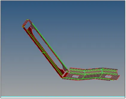
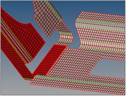
The former image shows Front truss 2, front truss 1 and right rail 1parts of the model and the later image shows the area where the connector needs to be created in order to attach these three parts.
STEP 1: Select 1D/2D > connector > Spot option.
STEP 2: Now select the location where the weld needs to be created by clicking ‘node list’.
STEP 3: Tick the checkbox of ‘retain nodes’ option to retain the position of nodes, while creating and realizing a connector.
STEP 4: Specify the spacing value as 5 (Since element size = 5) and select the ‘comps’ option under ‘connect what’ in order to create the connector between those two component.
STEP 5: Specify the number of layers (Number of components) to be welded under ‘num layers’ option. In this case, we create the connector in order to attach 3 components therefore number of layers is selected as 3.
STEP 6: Specify the tolerance value based on the distance between the two components. In this case its 4.
STEP 7: Select the type as ‘weld’.
STEP 7: Click on create button to create the spot weld connector.
STEP 8: Sometimes mesh is altered while creating the connectors. If this happens, then fixed then altered mesh by remeshing those elements or by other ways.
The component will be connected as shown below:
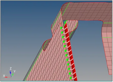
PART-4 : Front_truss_2, Front_truss_1 & Left_Rail_1:- Hexa (Adhesive)
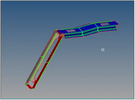
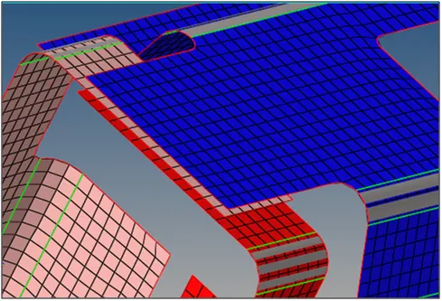
The former image shows the Left rail 1, front truss 1 and front truss 2 parts of the model and the later image shows the area where the connector needs to be created in order to attach these parts.
STEP 1: Select 1D/2D > connector > Seam option.
STEP 2: Now select the location where the connector needs to be created by clicking ‘node list’.
STEP 3: Tick the checkbox of ‘retain nodes’ option to retain the position of nodes, while creating and realizing a connector.
STEP 4: Specify the spacing value as 5 (Since element size = 5) and select the ‘comps’ option under ‘connect what’ in order to create the connector between those two component.
STEP 5: Specify the tolerance value based on the distance between the two components.
STEP 6: Select the type as ‘hexa adhesive’.
STEP 7: Click on create button to create the hexa adhesive connector.
STEP 8: Sometimes mesh is altered while creating the connectors. If this happens, then fixed then altered mesh by remeshing those elements or by other ways.
The component will be connected as shown below:
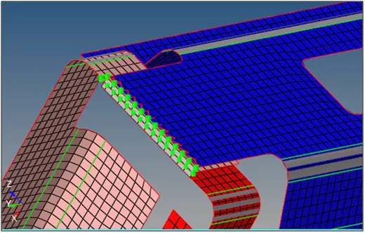
PART-5 : Rear_truss_2 & Right_Rail_2:- Bolt Connector
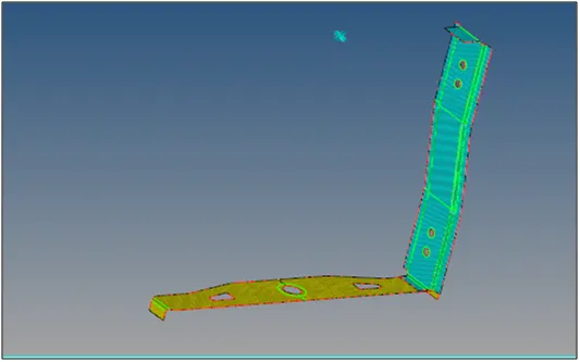
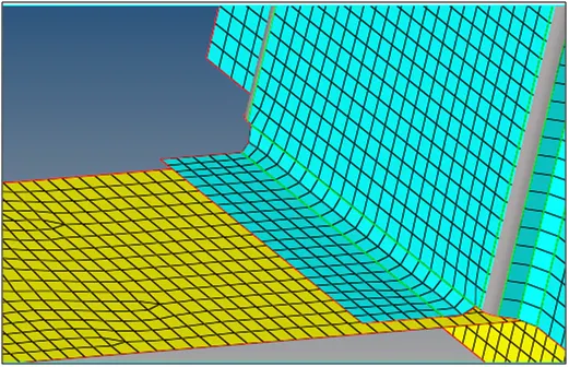
The former image shows the Rear truss 2 and Right rail 2 parts of the model and the later image shows the area where the connector needs to be created in order to attach both parts.
STEP 1: Select 1D/2D > connector > Bolt option.
STEP 2: Now select the location where the connector needs to be created by clicking ‘node list’.
STEP 3: Specify the number of layers to be welded under ‘num layers’ option. In this case, since we have to attach two components therefore it should be 2.
STEP 4: Specify the tolerance value based on the distance between the two components. In this case its 4.
STEP 5: Select the type as ‘Bolt (general)’.
STEP 6: For the bolt connection we require hole and since there is no hole present in the geometry so we have to create it. Select the option as shown in figure below:

The hole will be created in FEA model alone not in the surface.
STEP 7: Click on create button to create the bolt connector.
STEP 8: Sometimes mesh is altered while creating the connectors. If this happens, then fixed then altered mesh by remeshing those elements or by other ways.
The component will be connected as shown below:
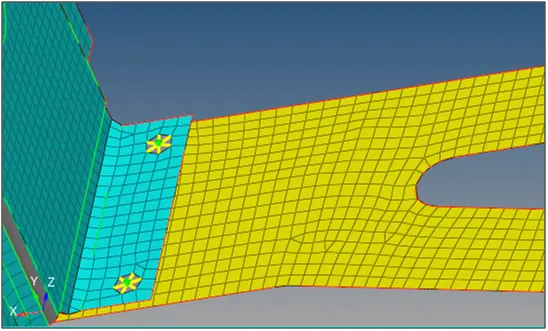
PART-6 : Rear_truss_2 & Left_Rail_2:- Bolt Connector
These parts are also connected in same way as part 4. The procedure for which is already discussed above.
The component will be connected as shown below
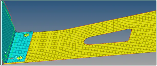
PART-7 : Right_Rail_1 & Right_Rail_2:- Spot-weld with Rigid Elements
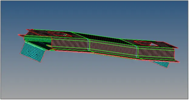
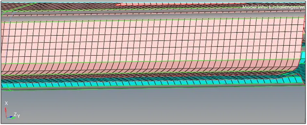
The former image shows Right rail 2 and right rail 1 parts of the model and the later image shows the area where the connector needs to be created in order to attach both parts.
STEP 1: Select 1D/2D > connector > Spot option.
STEP 2: Now select the location where the connector needs to be created by clicking ‘node list’.
STEP 3: Tick the checkbox of ‘retain nodes’ option to retain the position of nodes, while creating and realizing a connector
STEP 4: Specify the spacing value as 5 (Since element size = 5) and select the ‘comps’ option under ‘connect what’ in order to create the connector between those two component.
STEP 5: Specify the number of layers (Number of components) to be welded under ‘num layers’ option. In this case, we create the connector in order to attach 2 components therefore number of layers is selected as 2.
STEP 6: Specify the tolerance value based on the distance between the two components. In this case its 4.
STEP 7: Select the type as ‘rigid’.
STEP 8: Click on create button to create the spot weld rigid connector.
STEP 9: Sometimes mesh is altered while creating the connectors. If this happens, then fixed then altered mesh by remeshing those elements or by other ways.
The component will be connected as shown below
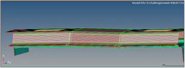
PART-8 : Left_Rail_1 & Left_Rail_2:- Spot-weld with Spring Elements
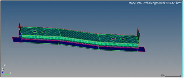
These parts are attached with the spot weld spring connector in the same way as discussed for part 7. The only difference is that in step 7, we have to select the type as ‘spring’.
The component will be connected as shown below:
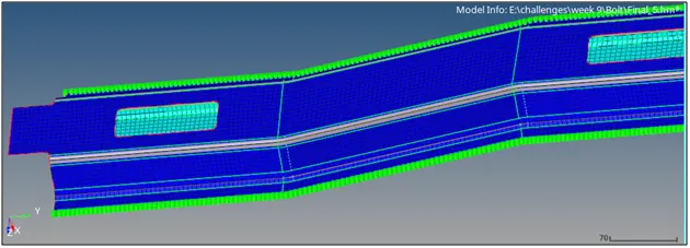
Now the parts which are left such as rear truss 2 and rear truss 1 are connected with seam connector with rigid element and the reif plate is connected with the front truss 1 and front truss2 parts by spot weld connectors.
RESULT: Link of the final model is attached below:
https://drive.google.com/file/d/1jOplK7e83zpARRZY5Hqy7QgbuAm06l4k/view?usp=sharing