Week 9 - Challenge 3 - Bumper
Challenge 3 - Bumper
Aim: Create the bumper plastic component through class A surface and then perform draft analysis.
Theory:
Class A Surface: Class A surface is a surface made by the designer specifically in automotive design which is the aesthetic part of the body and given as input to the plastic designer to work on it.
Class B Surface: It is the surface which is below the class A Surface at the thickness of the part. This surface contains the engineering features of the part.
Class C Surface: The surface which joins class A and class B Surface is called Class C Surface.
Tooling Axis: Tooling axis is the direction in which the core and cavity opens. If we are using proper tooling axis we can avoid adding side cores thus the cost of the manufacturing of the component can be reduced.
Generally tooling axis is decided from the natural axis of the design that is tooling axis is analyzed with the X,Y and Z axis of the system. If the axis does not clear the draft analysis, the next step is to look for the surface in which the tooling axis can be created such a way that the tooling axis is normal to the surface taken. If this two methods don't work then we use bisecting method.
Bisecting method: It is a method used to create tooling axis, by bisecting two lines from the surface and from two planes and then bisecting them and creating tooling axis.
Her in our case we use axis and direction method to create tooling axis.
Draft Analysis:
From draft analysis , we can verify the draft angles, examine the angle changes within a face ,as well as locating parting lines, injection and ejection surfaces in the parts.
Step 1: Ensure that the customized view parameter is enabled and the material mode is opted in view mode selection.
Step 2: Now go to insert>analysis>feature draft analysis
Step 3: Drag the axis bar to the tooling direction of the part
Step 4: Check the Draft
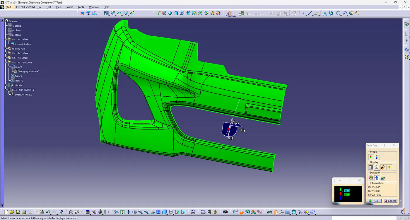
Surface will be in green if the draft angle is more than 3 degrees, blue if the draft angle is between 0 to 3 degrees and red if the draft angle is less than zero degrees.
Procedure:
Creation of class A Surface:
1. Class A Surface is obtained as input
2.Join all the surfaces to obtain class A surface if numerous surfaces are given as input and ensure no gap is present between the surfaces .This a class A Surface is obtained. Here the provided surface is completely joined and can be taken as class A Surface.
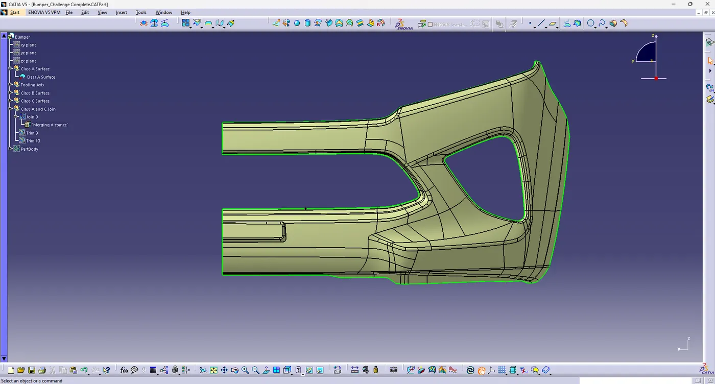
2. Creation of tooling axis:
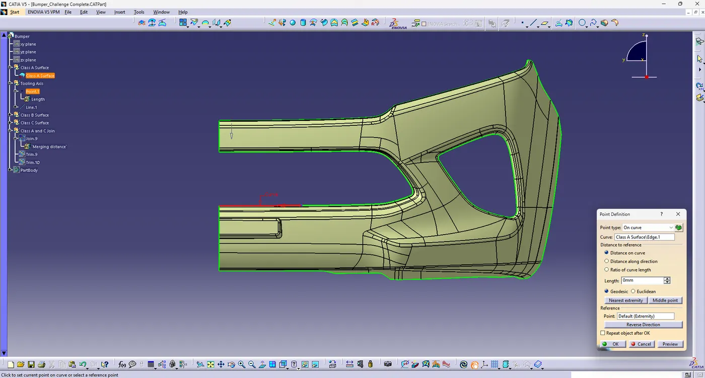
1. Here one of the straight edges of a class A surfaces is selected and point is created at the center of the edge.
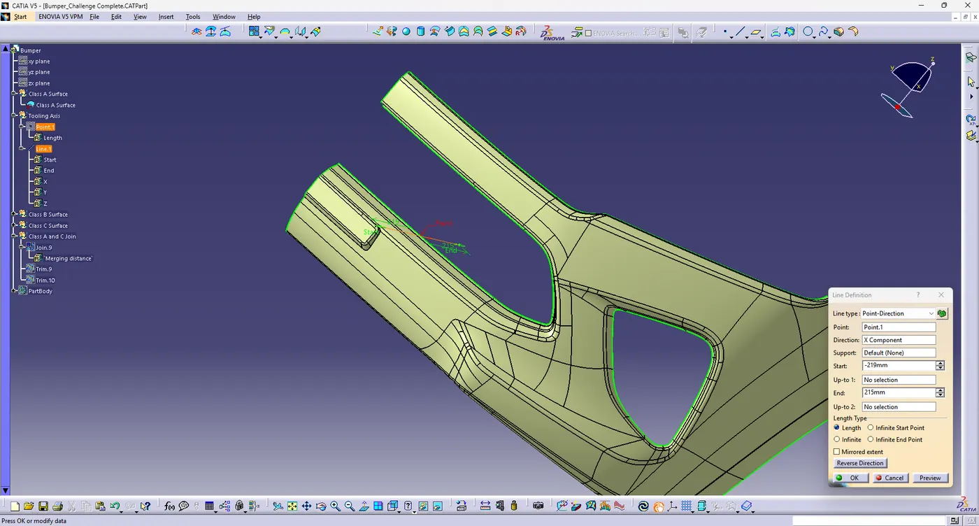
2. Then a line is drawn in the point created and point and axis option is used to create a line. And this is used as tooling axis as the draft analysis is also cleared.
3. Creation of class B Surface:
1. Class B Surface is created by using multiple extract to extract all the class A surface in one go and then offsetted to a direction of the thickness to a thickness of 3mm.
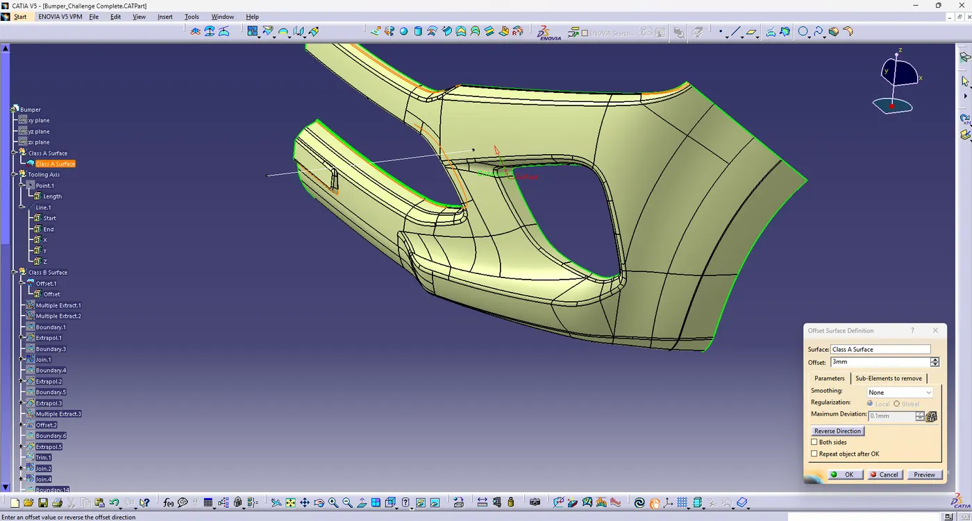
2. Small filleted portions are avoided from extraction and all the other surfaces are extracted and offsetted. These small fillets are avoided because as we offset the for 3mm they cannot be created by catia and gives us error message.
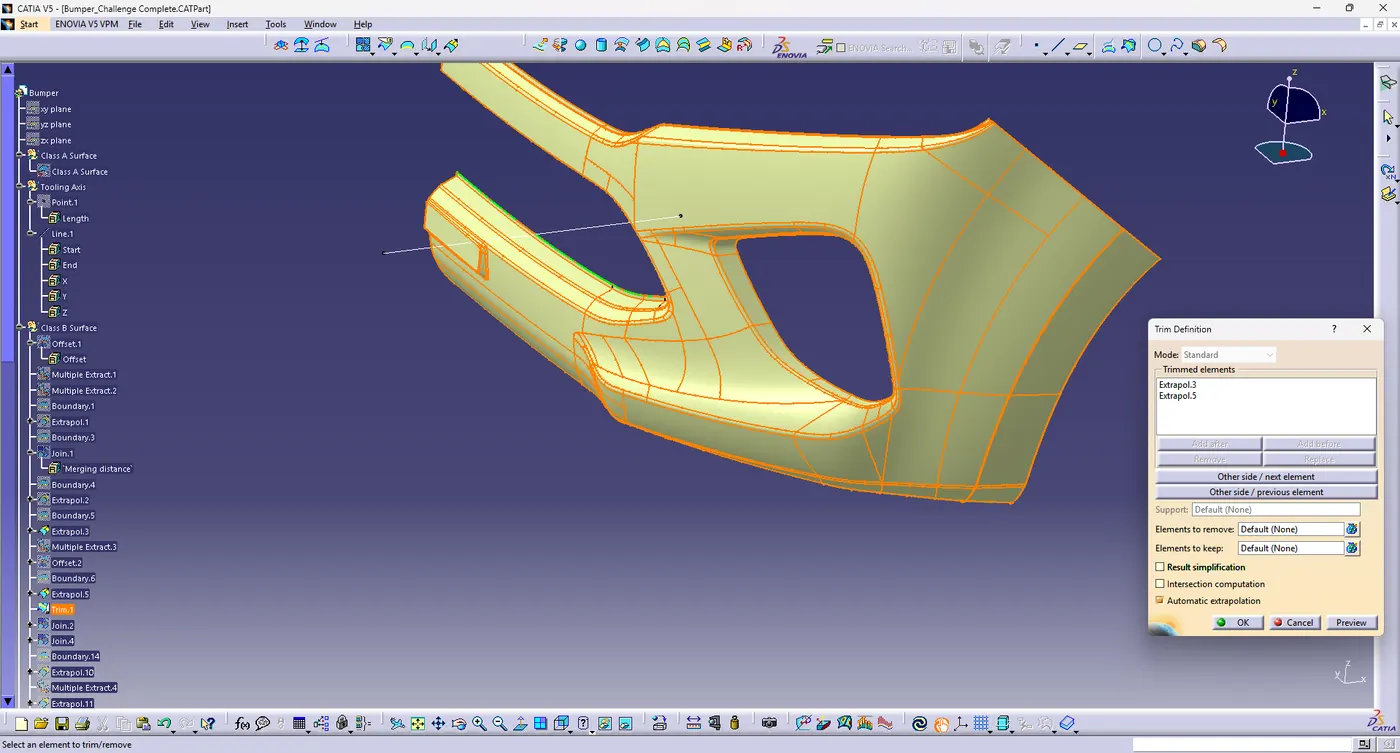
3. Similarly other surfaces are extracted avoiding the fillets and offsetted, extrapolated and trimmed with the main surface to get proper B Surface.
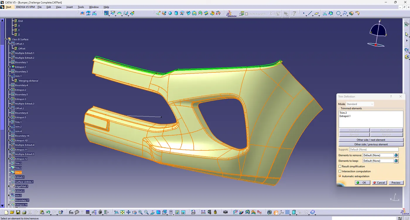
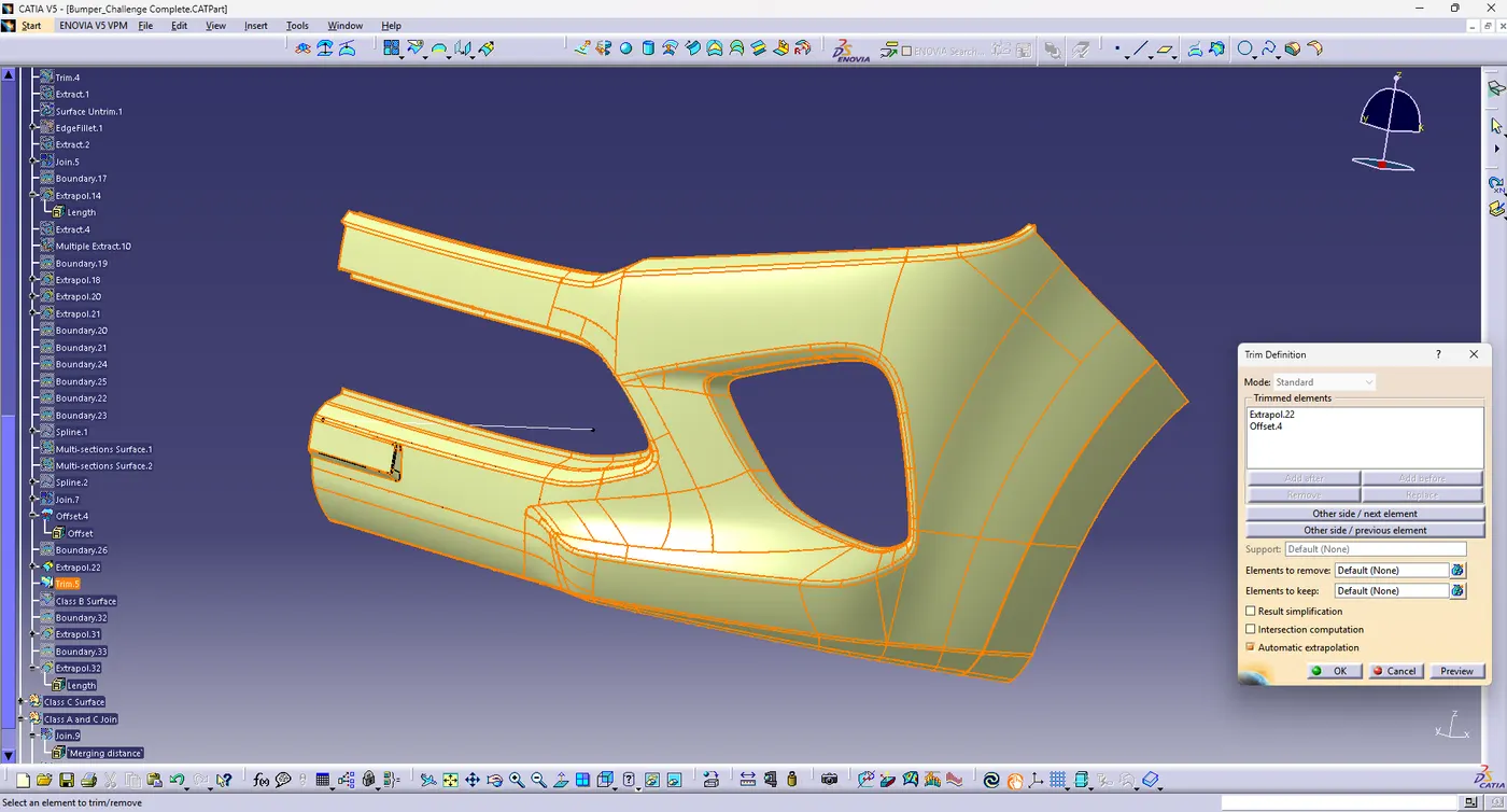
4. Then fillets are measured from class A Surface and appropriate fillets are provided for class B Surface by adding or subtracting the thickness of the component to obtain correct thickness everywhere.
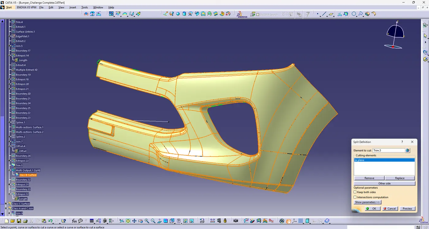
4. Creation of class C surface:
1. Now Class C surface has to be created and it is created from the boundaries obtained from the class A surface. This boundary is provided as the input curve for the sweep command. Using the sweep command, class C surface is created.
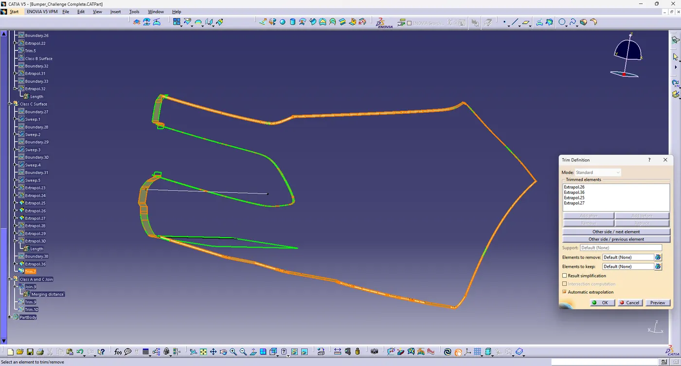
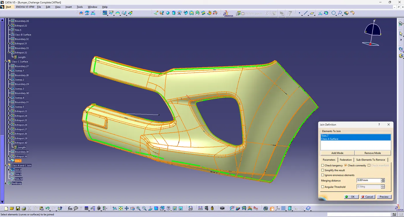
5. Joining a class A and Class c Surface
So when the class C surface is created then both the class A and Class C Surface are joined.
6. Creation of Closed surface
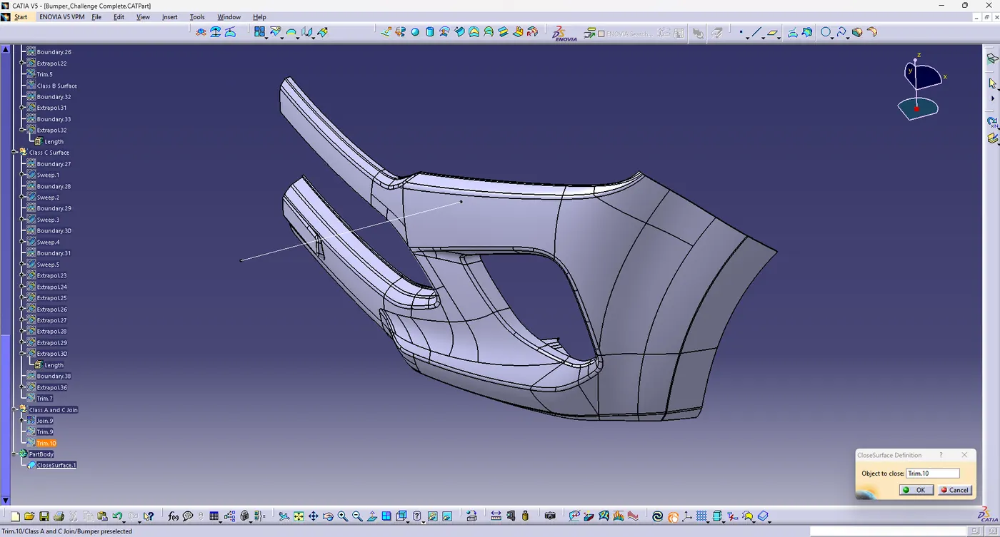
Then the joined surface is used to trim the class B Surface to create a closed surface.
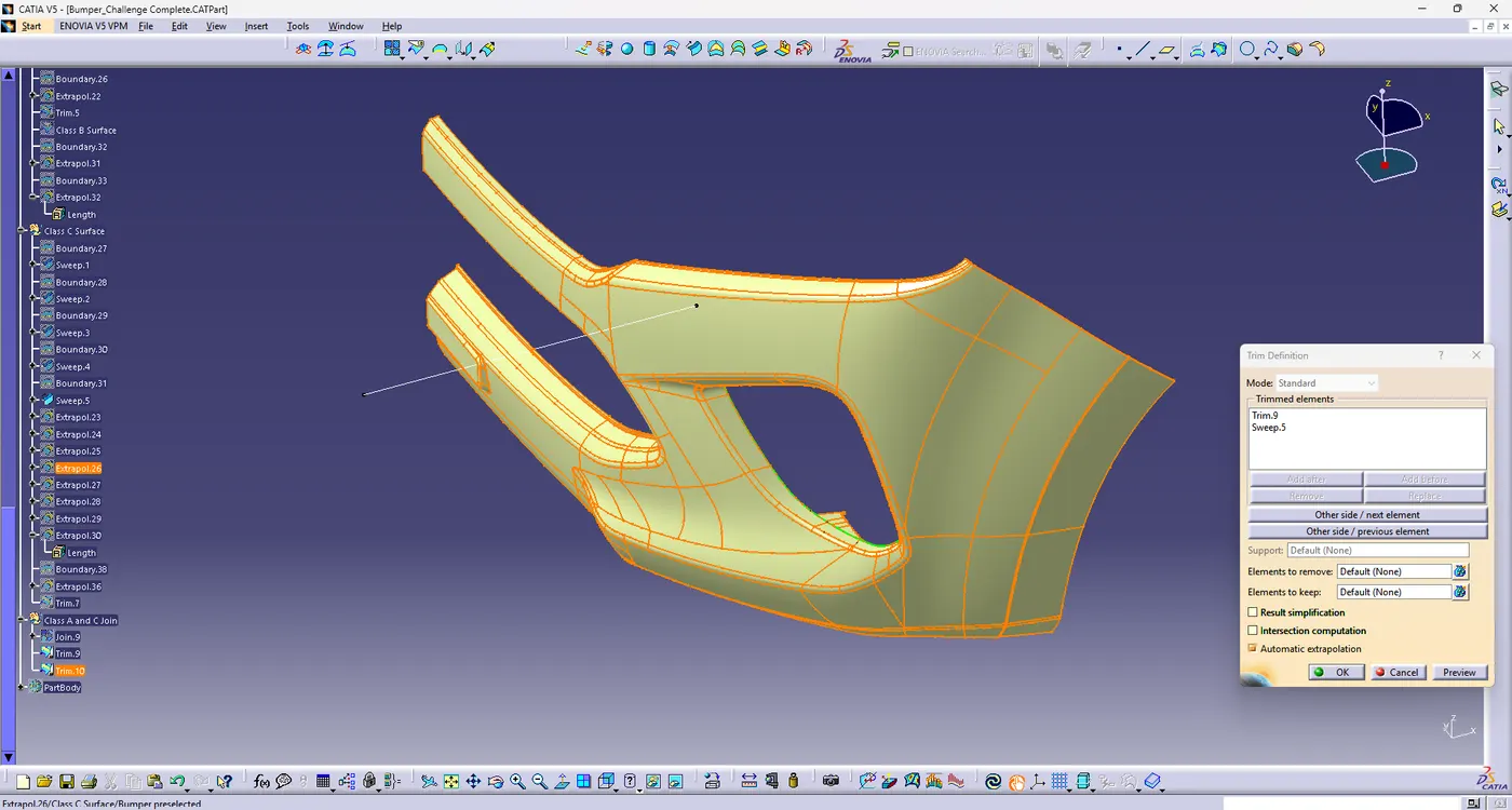
Once the closed surface is created and then the closed surface is created to a part body using the closed Surface feature.
Draft analysis of the part:
The obtained part is draft analyzed to check for the correctness of the obtained model by following the draft analysis procedure mentioned above.
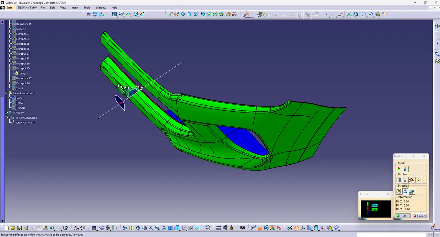
So the class A surface are obtained are in all green in color, which means the surfaces are clearing the draft analysis. The faces that are obtained in red/blue will be clearing the core side as the direction is reversed.