Week 9 - Challenge 3 - Bumper
DESIGN OF BUMPER USING CLASS A SURFACE
AIM:Design the bumper of a car using class A surface provided in CATIA software
OBJECTIVE:The main objective is to make use of the class A surface provided and generate the class B and class c surfaces and there by joining /trimming of the them leads to the final closed surface and apply the solid surface feature to obtain a solid body out of it
STEPS INVOLVED:
TOOLING AXIS CREATION
DRAFT ANALYSIS.
CLASS B CREATION
CLASS C CREATION
FINAL TRIM
SOLID BODY
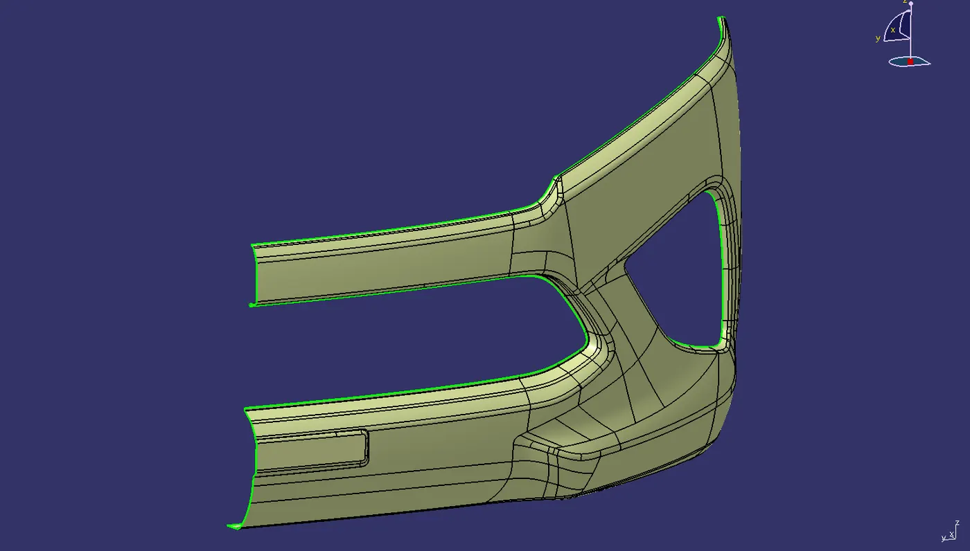
CLASS A SURFACE: Styling or A class surface are the terms used in plastic product design which means the surface of a component which is smooth( aesthetic) or visible side to human eye after the part is assembled. Generally this surface needs to be more asthetic and smooth for the customer attention
CLASS B SURFACE:
class B is basically referred as an engineering surface where lot of components like heat stakes, screw bosses,doghouses are designed It is the surface that lies beneath the class A to a thickness range of upto 3mm
CLASS C SURFACE:
Basically class C is the intermediate surface lies between class A and class B surface . It is the surface generated with the aid of class A surface.
COMMANDS USED:
Boundary
Extract
Offset surface
extrapolate surface
Sweep
Join
Multi section surface
spline
Point
Line
Trim
Multiple extract
Edge fillet
TOOLING AXIS CREATION:
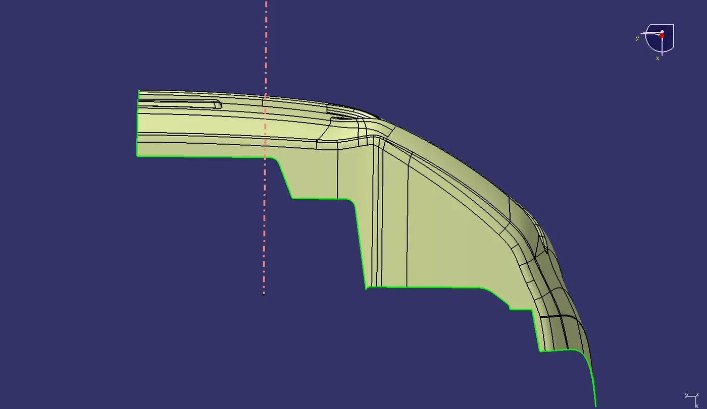
First of all check the boundary continuity of the class A surface using boundary feature or the join feature , then come to conclude the best view for the creation of the tooling aaxis so that all the components need to clear the draft in thet specified tooling direction
Methods employed for generating the tooling axis is
- Normal to surface method
- Point to direction method
- Bisecting method
For in case of bumper we generally choose the point - direction method for creating the tooling axis by choosing the best view to make the component completely visible for manufacturing
DRAFT ANALYSIS OF A SURFACE:
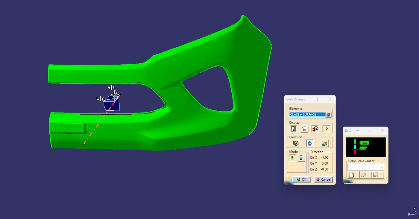
Draft analysis of the surface is carried to check if the surface or part can be manufactured with the required draft angle.
Draft angle is needed for the component to clear the core and cavity surface as it would have shrunk towards the centre while cooling.
The draft angle in this design is 3 degrees. As A surface is a single surface there won't be much difference in color.
CREATION OF B-SURFACE:
The A-surface is offsetted by 3.00mm as it is the thickness required.
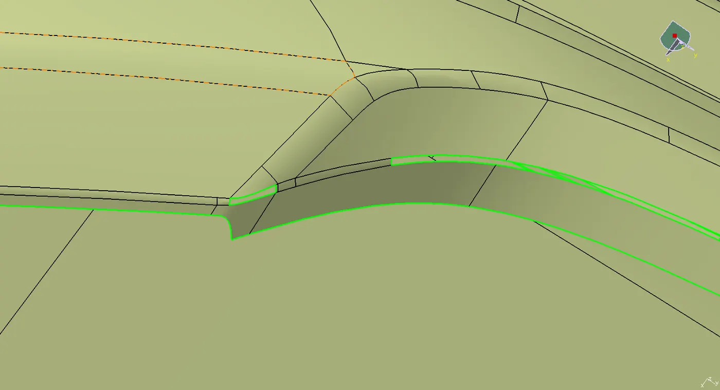
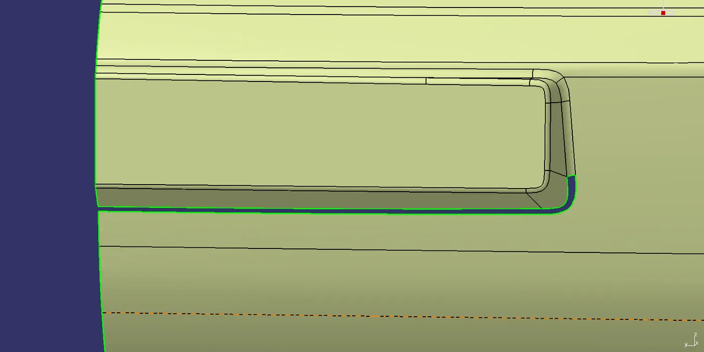
The Areas where the B-surface has issues are corrected by closing them using commands like Multi section, Sweep, Offset and extract.
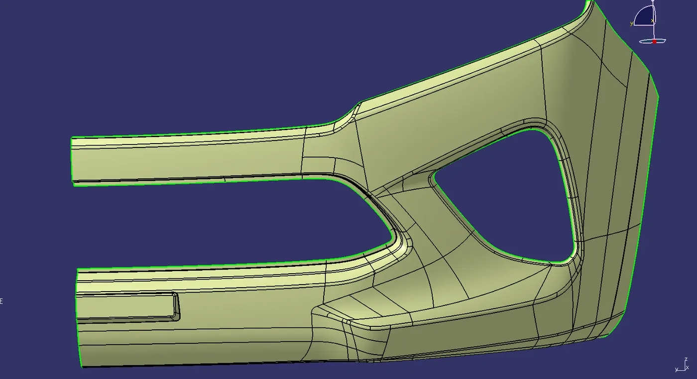
Finally, all the created surfaces are trimmed or joined together with offset surfaces done earlier. This created a single single surface which will act as the final B-surface.
B surface created is checked for any gaps or errors by creating a complete boundary
PATCH 01
PATCH 02
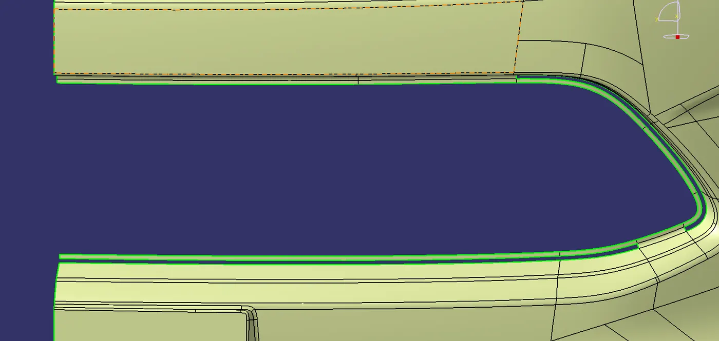
PATCH 03
CLASS B SURFACE
CREATION OF C-SURFACE:
The A and B surfaces are connected by another single surface which is called the C surface.
It is created by using sweep with A surface acting as the reference surface and curve created from the boundary of the same surface.
Sweep with draft direction is also used to create A-surfaces.
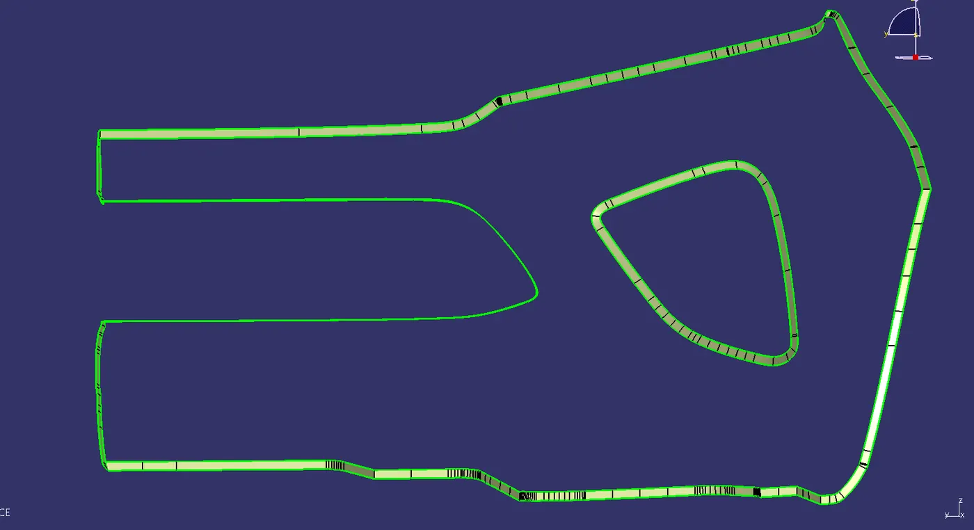
CLASS A AND CLASS C JOIN
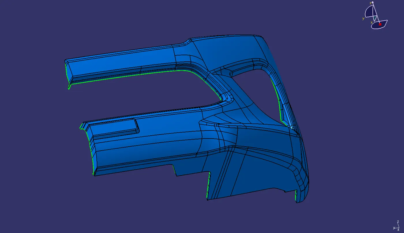
Then trim the class a and c join with classs b surface o get the final component
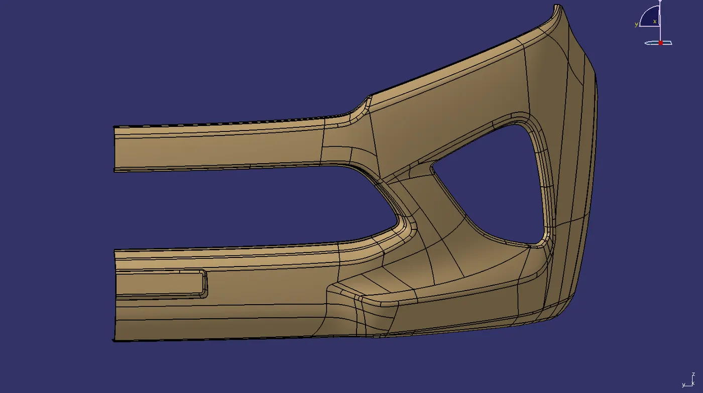
CREATION OF CLOSED BODY:
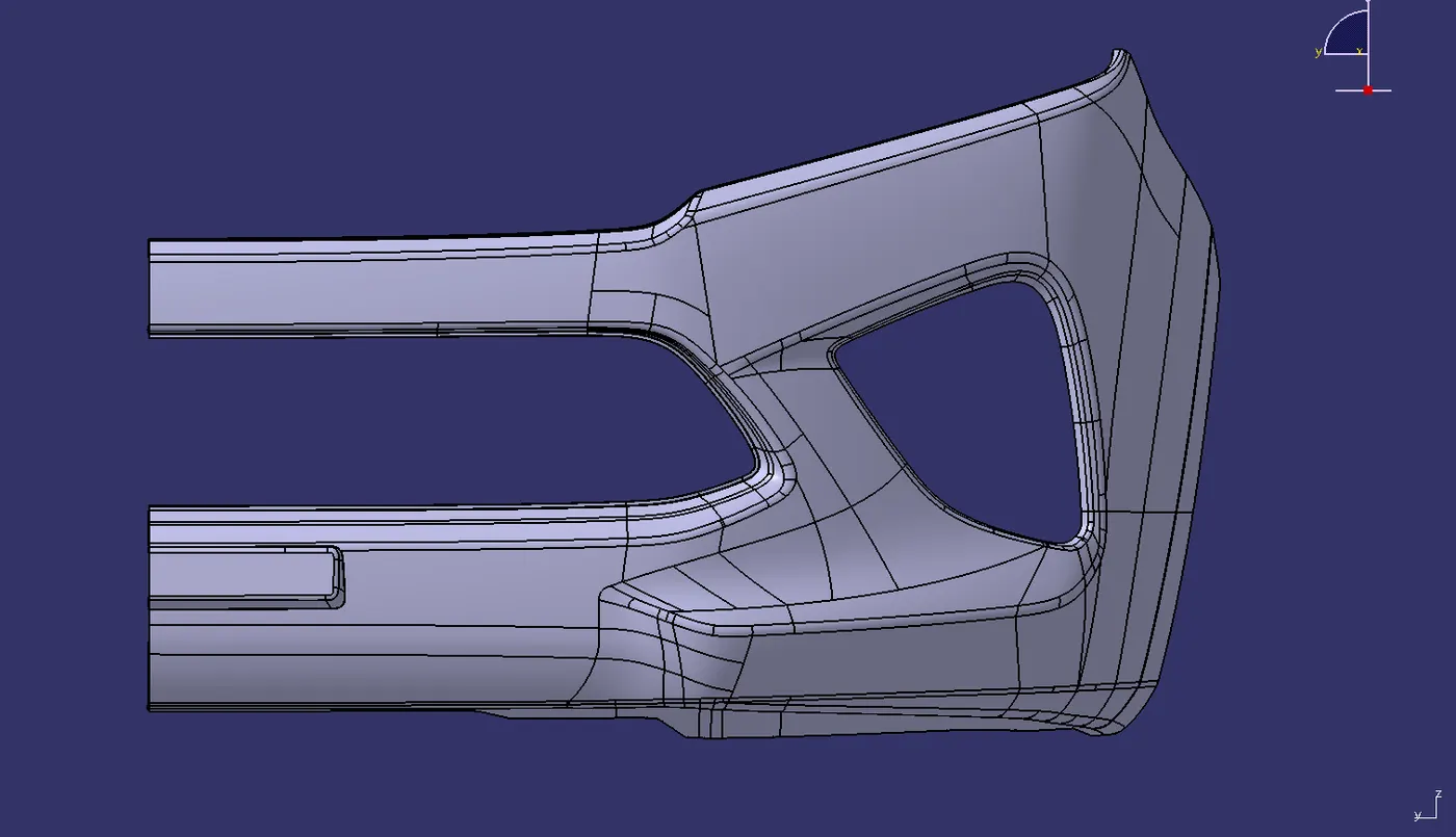
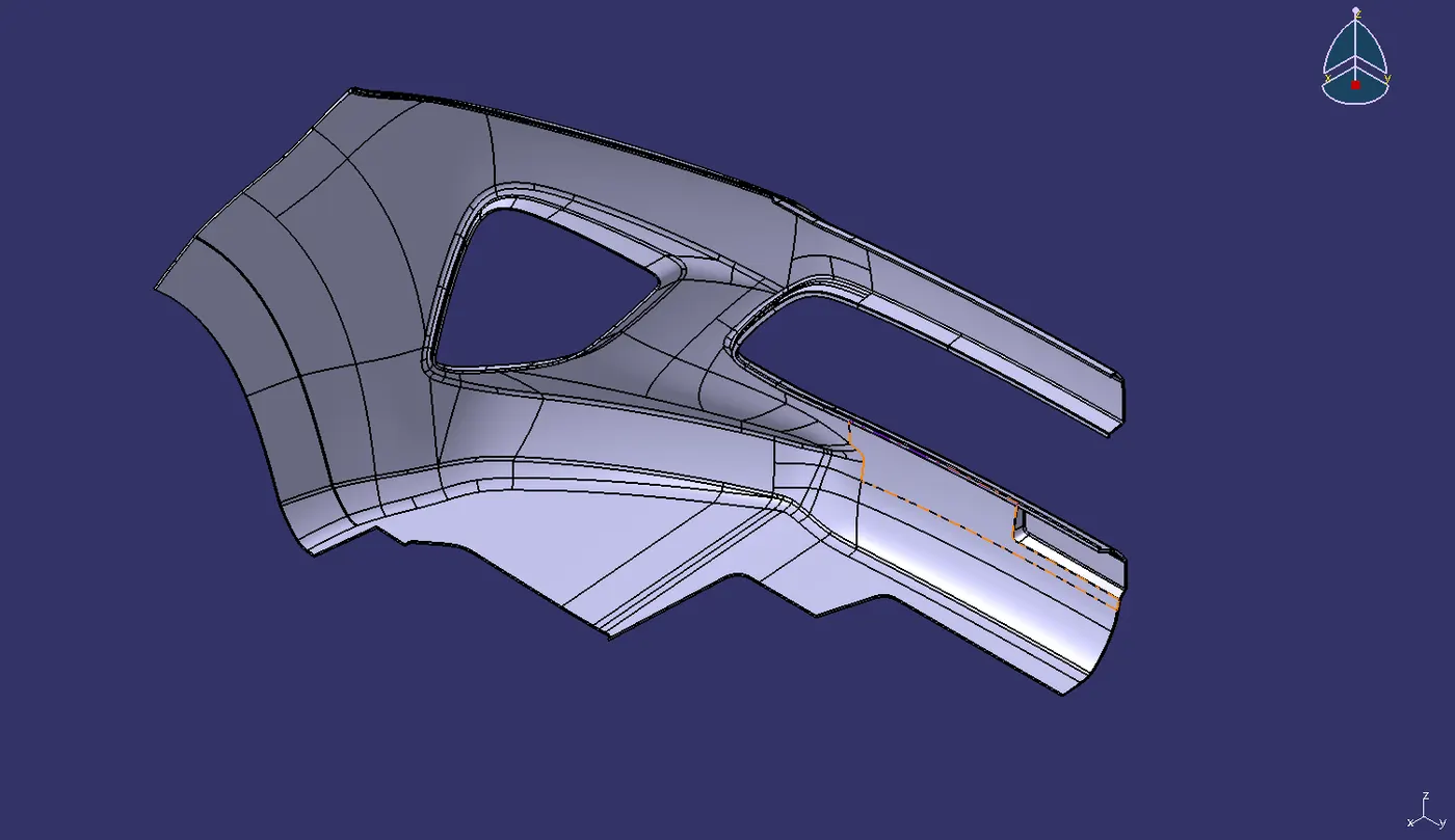
All the surfaces (A, B, C) are joined together to form a closed body.
Boundary is selected and the body is picked. Since an error popped up it can be understood that all surfaces are joined with each other to form a proper closed surface body.
Finally in part design workbench using closed body feature change it to sloid body.
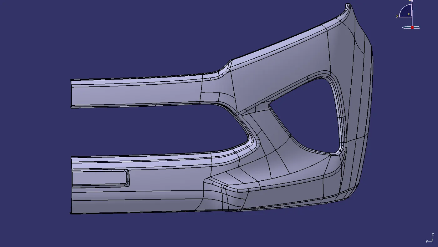
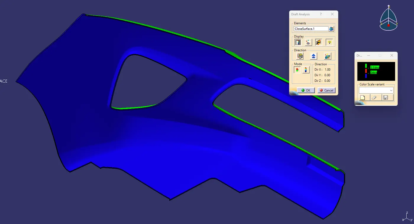
DRAFT ANALYSIS OF PART BODY:
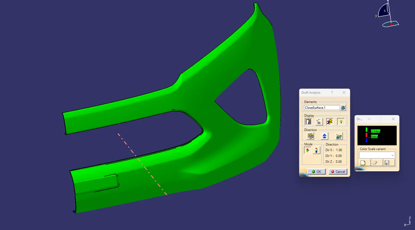
The final solid part body must be analysed using Draft analysis. This is done to check if all the areas of the body are satisfying the draft angle which is 3 degrees.
A draft angle is a taper applied to the vertical walls of the injection-moulded component to assist with releasing the part from the Mold.
Draft angles are a required feature of injection-molded custom parts. A functional part for injection molding must have draft angles that face both the cavity and core sides. This will reduce the risk of damage to the parts and ensure that they can be ejected from the machine.
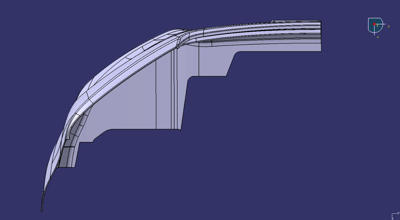
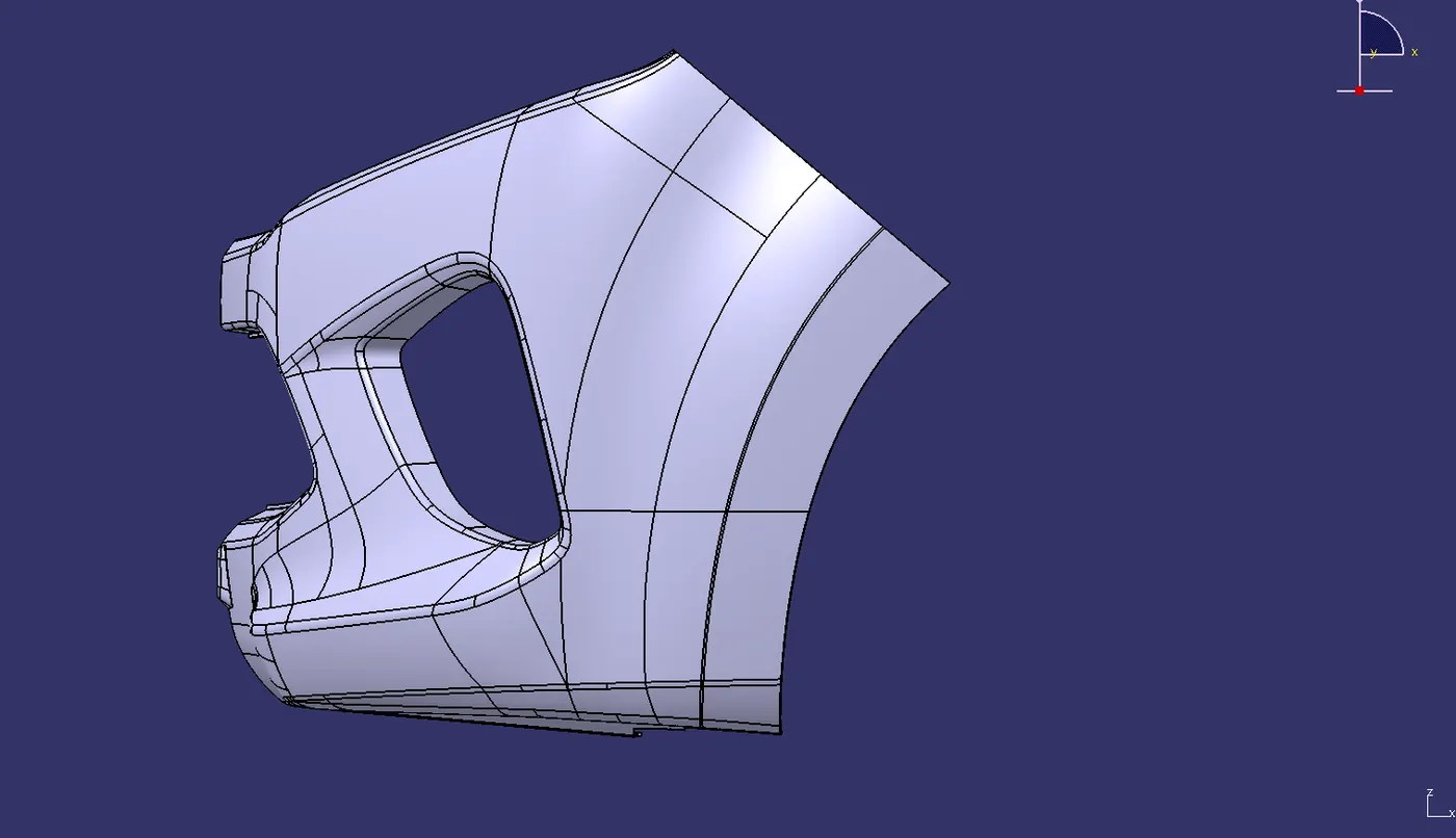
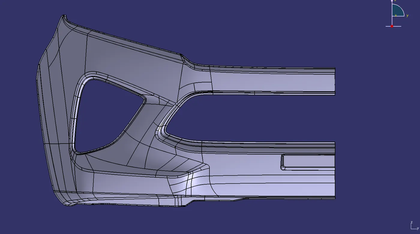
VIEWS:
CONCLUSION:
The Draft analysis of the component showed that the component is feasible to be molded without any issues.
Thus, it satisfies all design and manufacturing criteria needed for a proper part.
This concludes the report of design of bumper body.