Week 9 - Challenge 3 - Bumper
week 9 challenge:
bumper challenge:
Aim:
To Create the bumper Plastic component through the given Class-A surface. To begin with, the tooling axis for the given Class-A Surface should be created meeting the requirements of the draft angle and at the end perform the Draft analysis on the model.
software used:
catia v5 R20
procedure:
download the given class A surface, then open it on the catia v5.
CLASS A SURFACE:
using healing command heal the gap between the surface to get a plane surface.
using join command join the given class a surfaces into a single surface.
using a boundary command in surface workbench, check whether it is joined properly or not.if not try to fix it.
here is shows the class A surface.
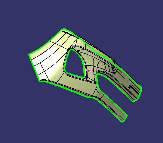
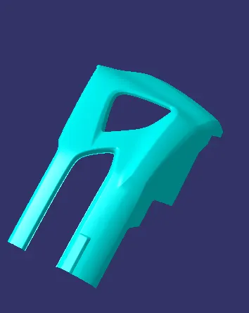
TOOLING AXIS:
creation of tooling axis . check for the plane which should be easy to create using injecton moulding and choose a hole slot or a plane surface .
then create a point in it and a dummy tooling axis. then, check for a parallel and slope surface. using a intersect command draw a intersecting line of x and y separately.
then draw a tooling axis for x and y separetely using a bisecting line .
here there is a complex surface, so put a point at anywhere and draw a line. then draw a tooling axis as shown below.
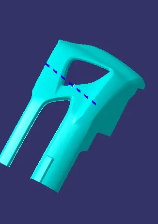
dark blue line indicates the tooling axis.
DRAFT ANALYSIS:
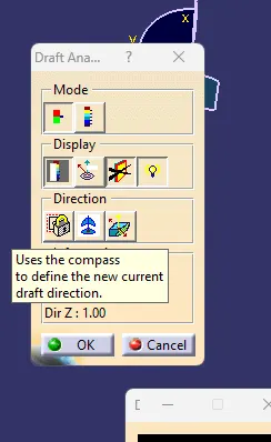
for draft analysis, in surface workbench click on insert>analysis>feature draft analysis as shown below:
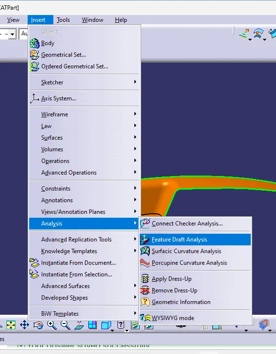
now click on compass to create c compass and place it on the tooling axis.
click on the class A surface to check the draft in the surface.
from the below figure it shows green which means it has a draft of more than three angle.
because less than three degree angle was difficult to manufacture.
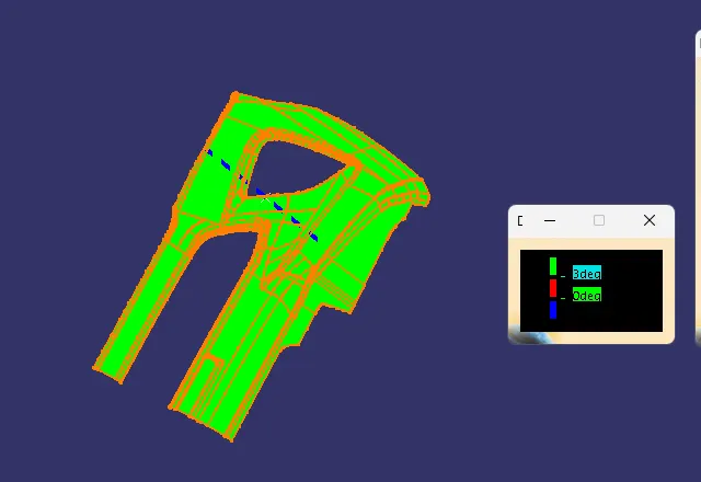
if the draft angle is less than three degree change the tooling axis angle or position and try it.
SURFACE B :
for creating a class b surface.
for this challenge, the complex bumper class a surface is directly offset to the thickness of the component which is 3mm as shown below.
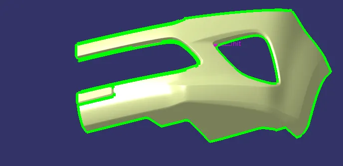
here we see a lot of patch and missing surface in between the offset surface. it is due to the larger radius of surface cannot be offset properly. so it is needed to correct the patches.
in this bumper it contains five correction patches in it. it is as following.
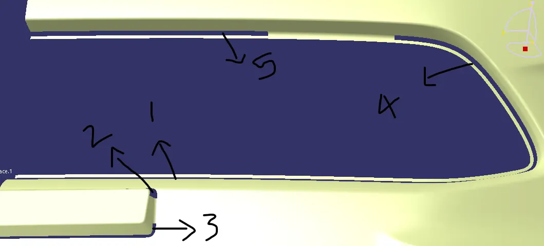
correction 1:
firstly extract the edges of the surface or using a boundary command create a boundary on four side then using a multisection command or fill command create a missing surface.
here using a boundary tool boundary of the walls are get, then using a fill command it is filled and finnally joined with the surface.

the red dotted line shows the boundary of the missing surface.
now using multi section command create a surface and join command join the correction 1 and the offsetted surface.
same like this all the patches are corrected
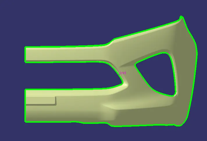
here it shows the CLASS B SURFACE.
note:
to check the clas B surface.create a boundary on it . if the booundary was along the corner it is perfect if not check it.
CLASS C surface:
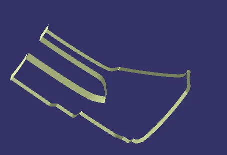
creating a class c surface firstly create a boundary along the class a surface. then using a sweep command sweep it.
for this boundary two individual boundary are created and then join together.
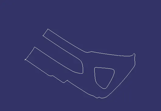
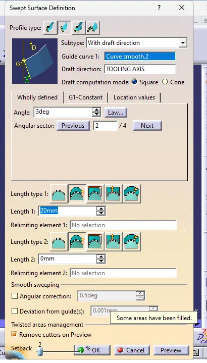
after creating a boundary, sweep it with draft direction as shown below for a surface which is perpendicular to the tooling axis.
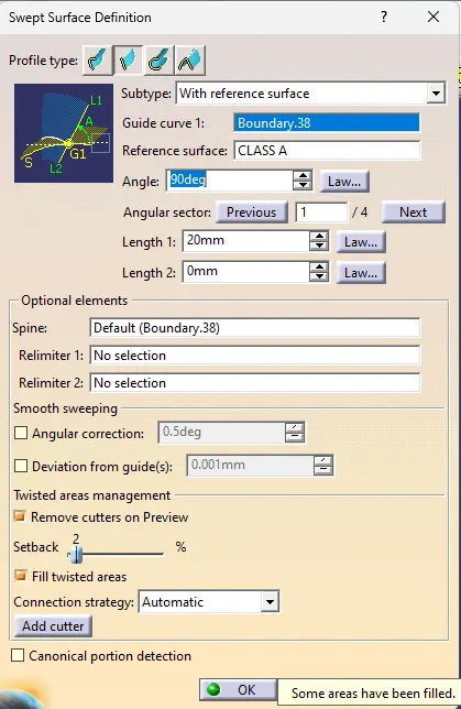
for parralle surface with tooling axis.
after sweep the surface would be like this.
after creating a class c surface. using a join command join the CLASS A and CLASS C surface to get a joined surface as shown below.
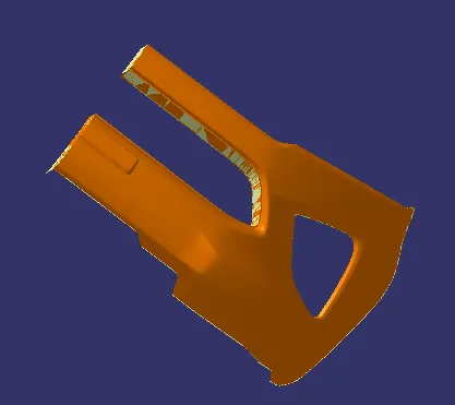
FINAL OUTPUT:
then trim the joined surface of A and C to the the classB surface to get a final output as shown below:
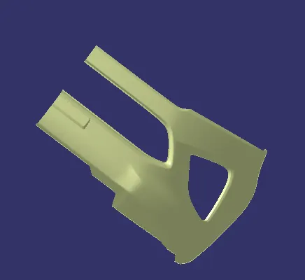
note: click on boundary command and click on the final trim surface . if there is no boundary and shows warning. the final trim is a closed surface.
other wise there is a gap between them it is nedded to correct it.
if there is no boundary only your final surface will become closed body.
now, from the part design. create a solid body
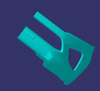
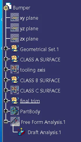
tree structure:
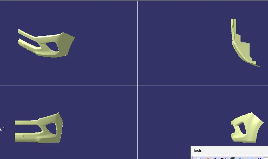
ALL views:
conclusion:
from the above, Created the bumper Plastic component through the given Class-A surface.
the catpart file is attached below.