Week 9 - Challenge 3 - Bumper
Bumper Report:
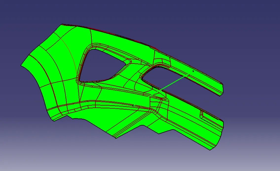
We create a Bumper plastic component from the given Class A surface in this challenge.
Start by creating a Tooling axis and do a draft analysis of the class A surface to verify the position taken for the tooling axis. Then offset the hole bumper and create a class B surface. While offsetting the Class A surface few portions won't be generting. Fill the gaps and provide the required fillet. Create a Class C surface by providing the Draft using the sweep tool on the Class A surface and join the created Class C and Class A surfaces. Extrapolate the class B surface edges to trim with joined class A and C surfaces and create a hollow bumper body. Use the close surface tool to create a solid body out of it.
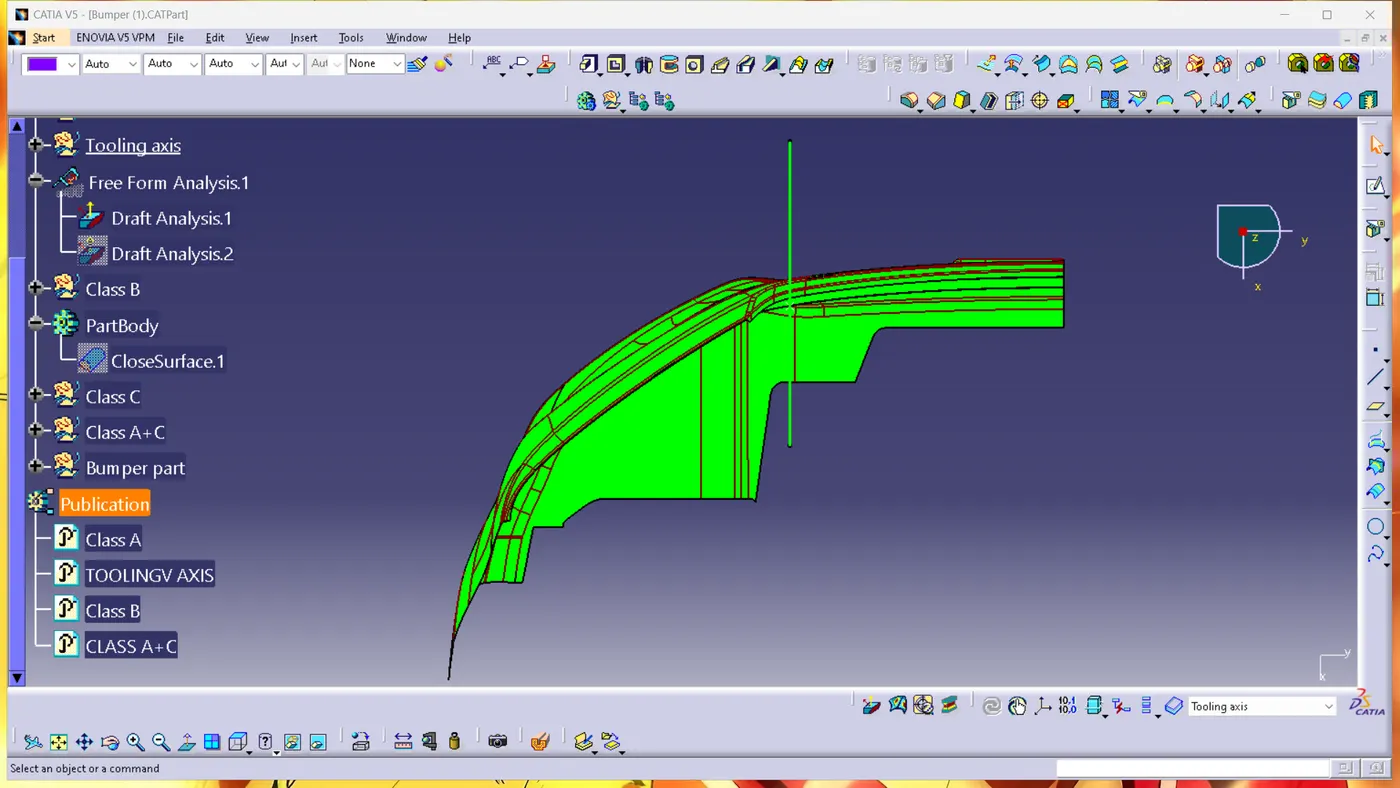
Tooling axis :
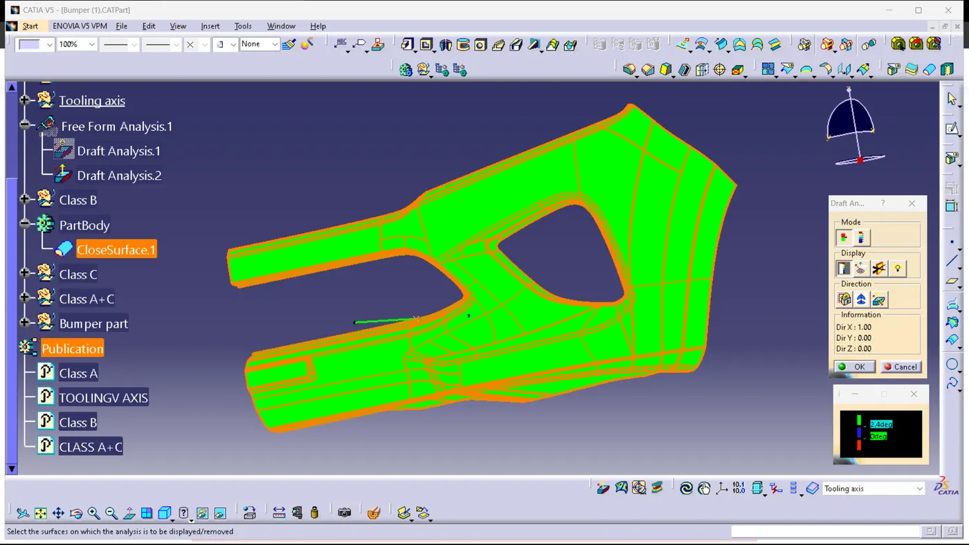
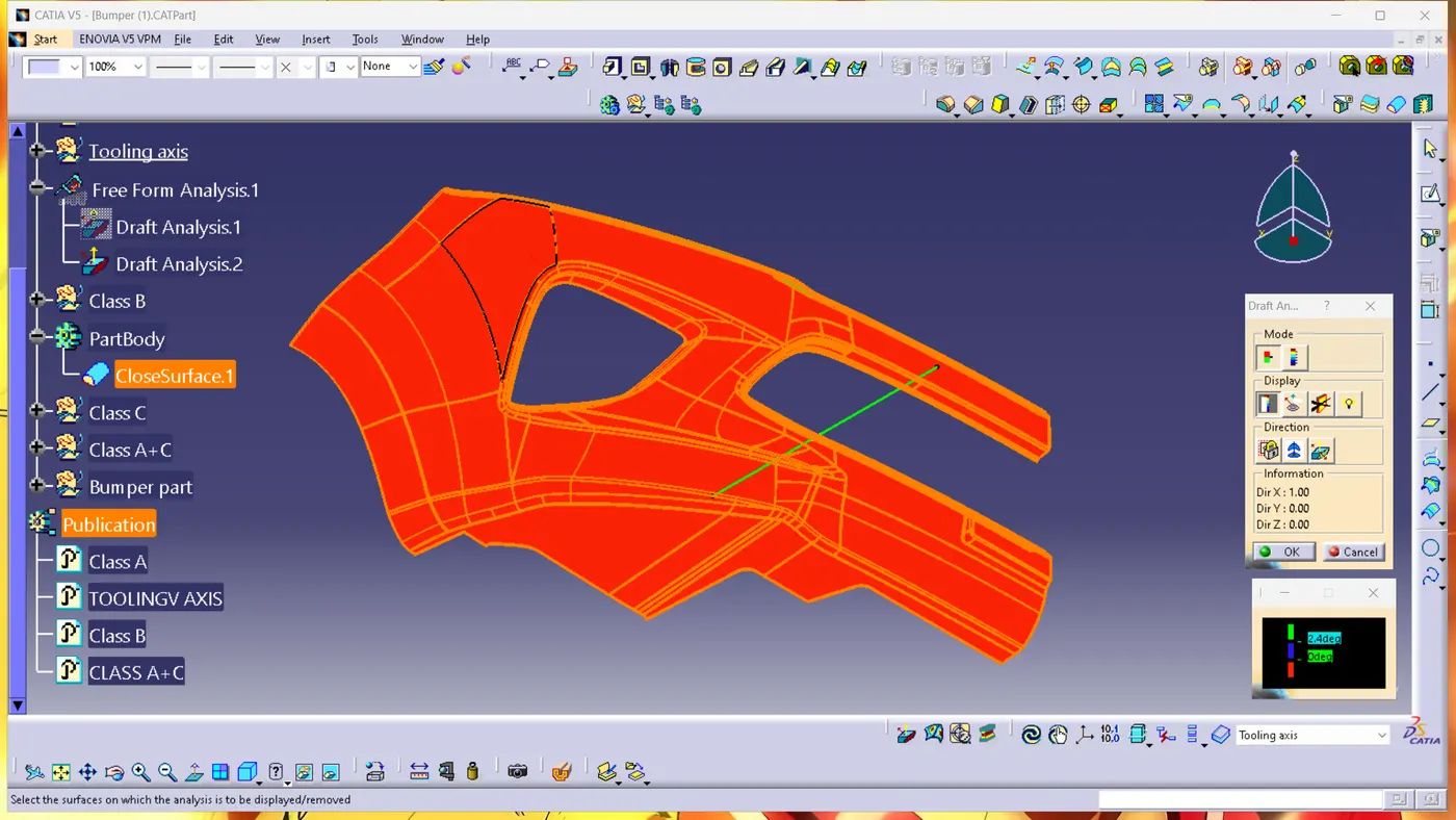
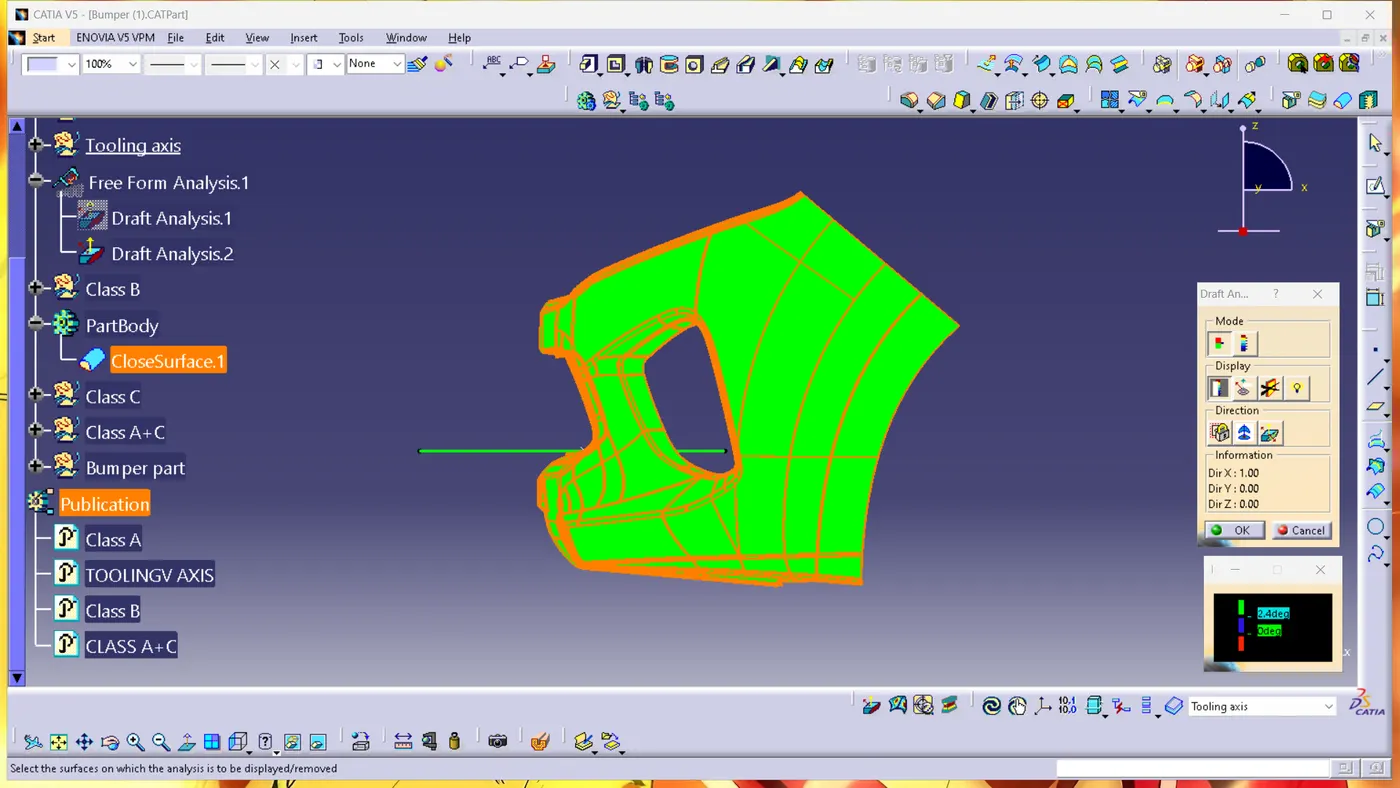
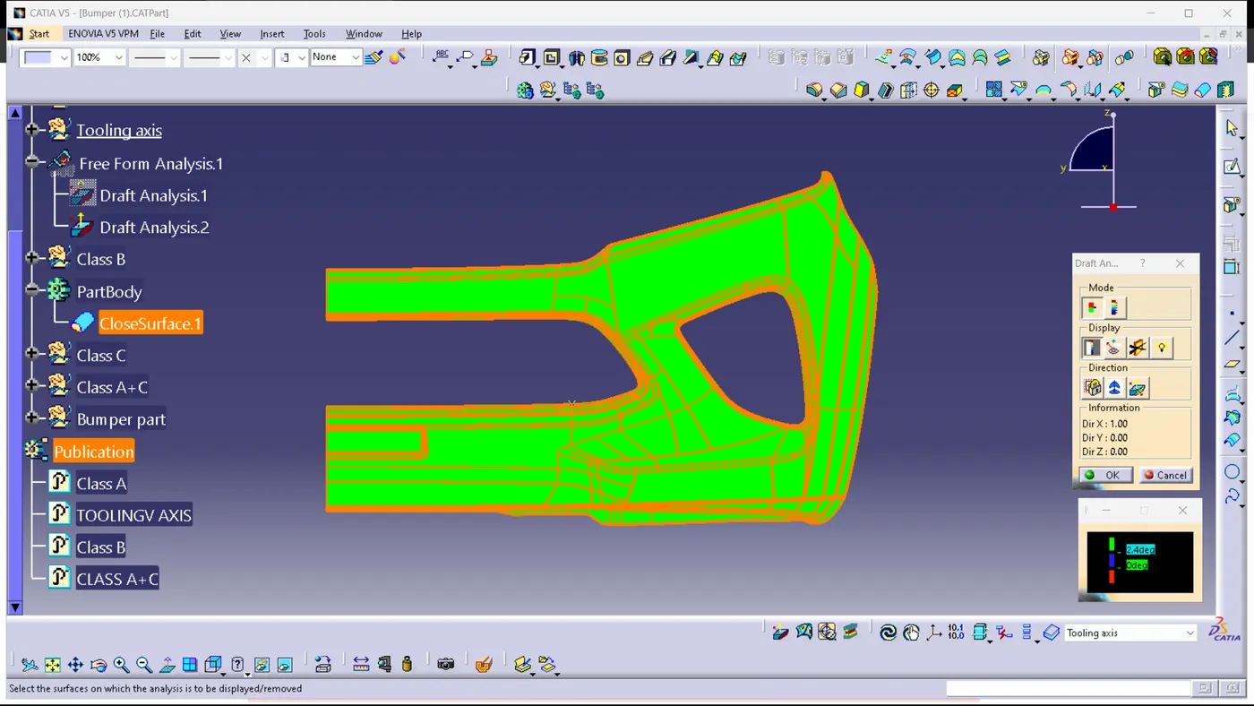
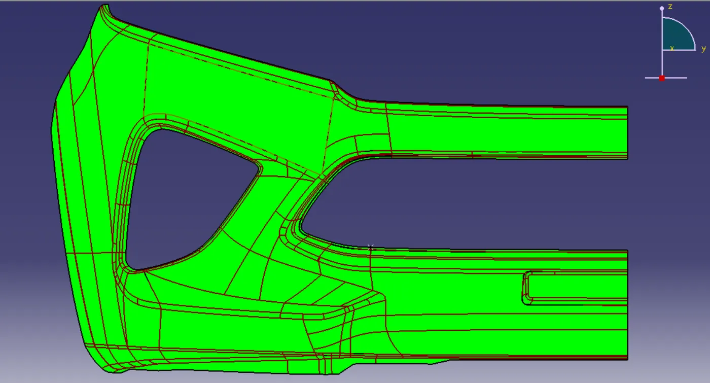
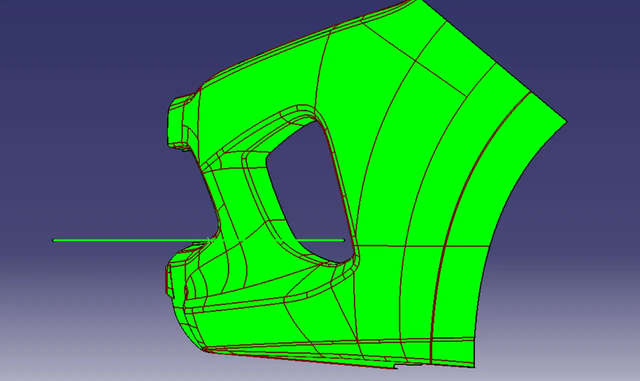
To create tooling axis, Check all 3 axes (X, Y, Z) to find which axis provides better view.
X axis shows more surface area compairing to other two axis.
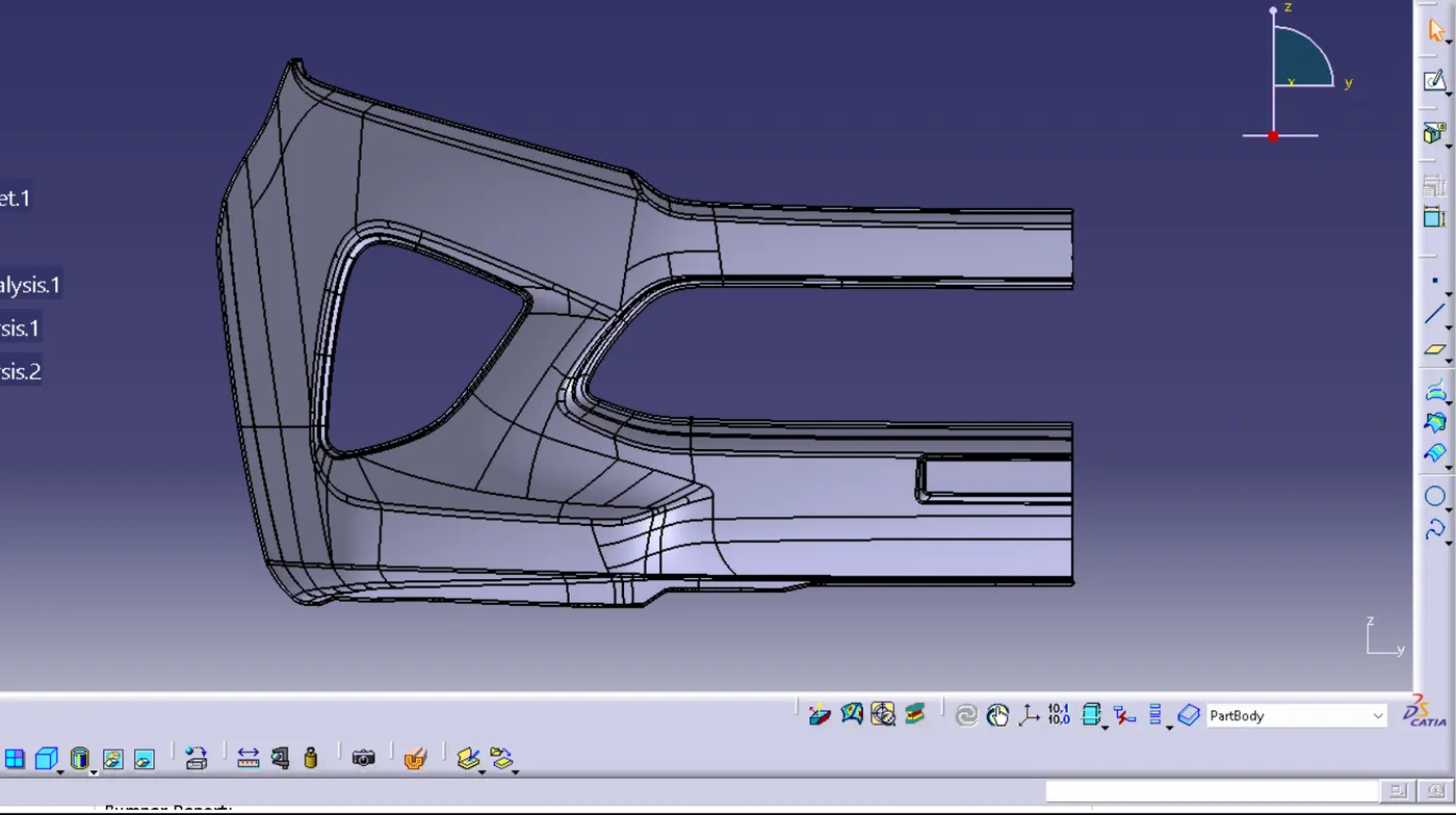
Create a geometrical set for tooling axis.
Create a point on any of the curve lines.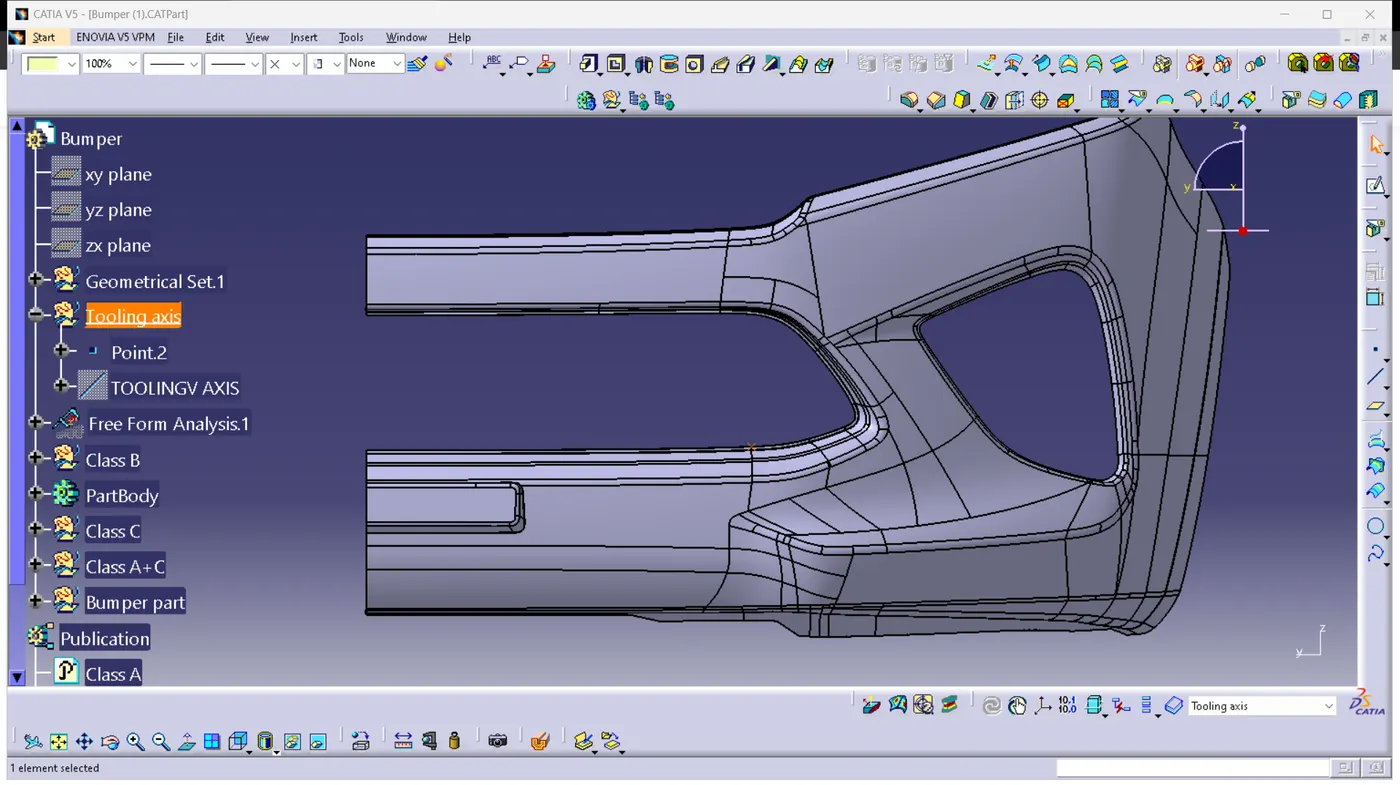
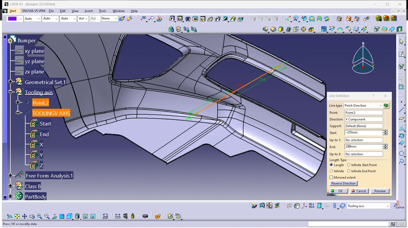
Create a line using point and direstion at that point created.
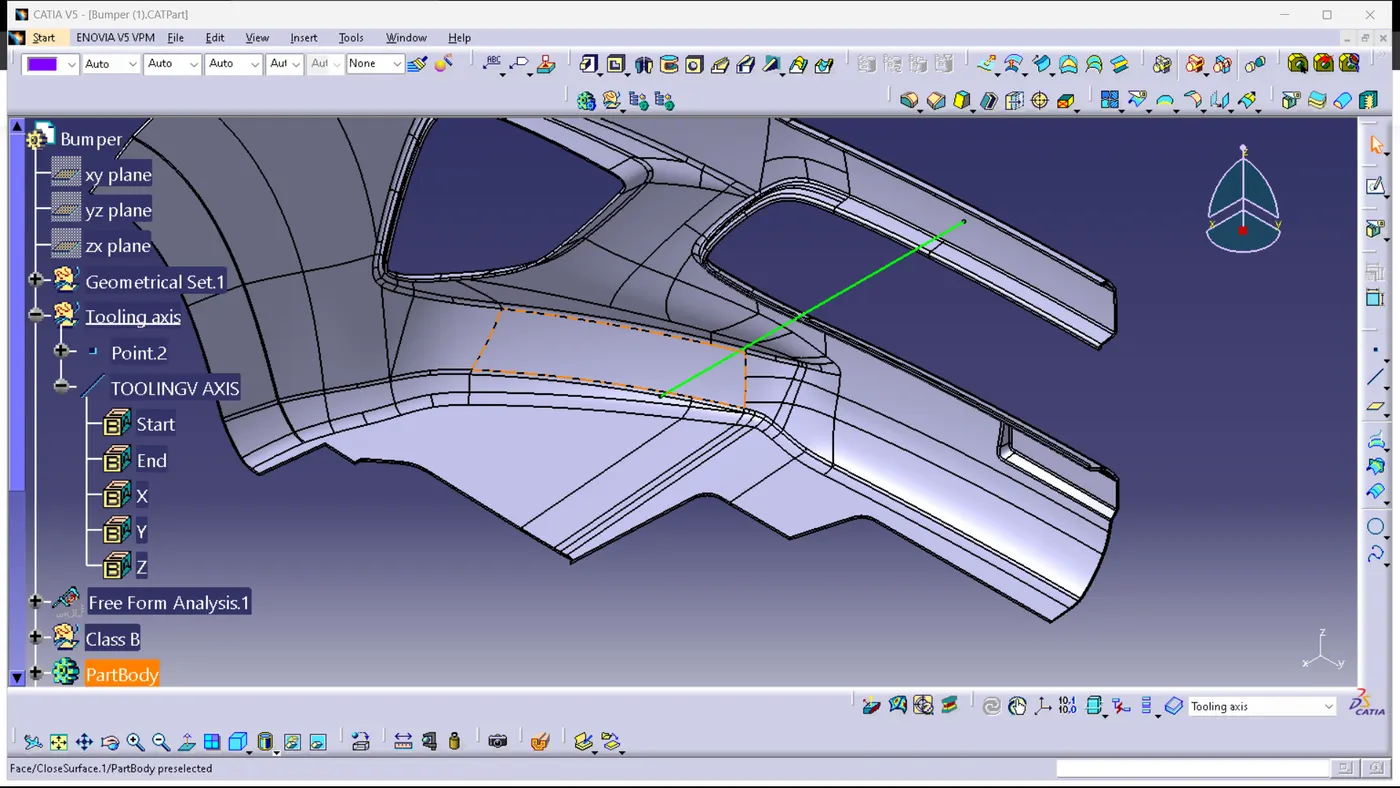
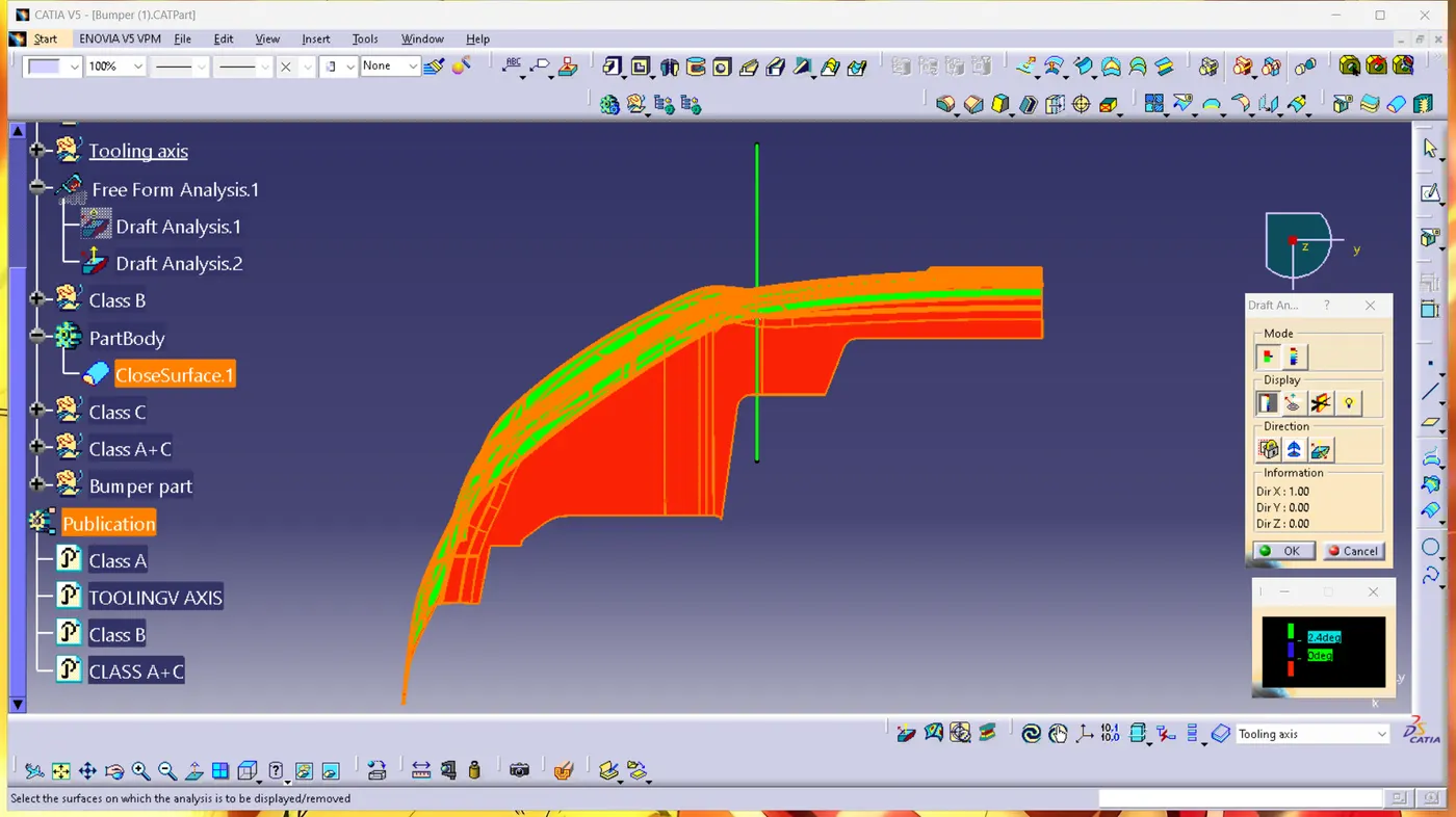
Draft analysis:
Change the view to  customization mode
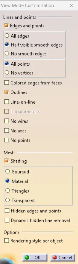
press ok
Select the draft analysis tool 
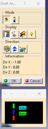
Select the compass option and adjust the compass over the draft tooling axis. 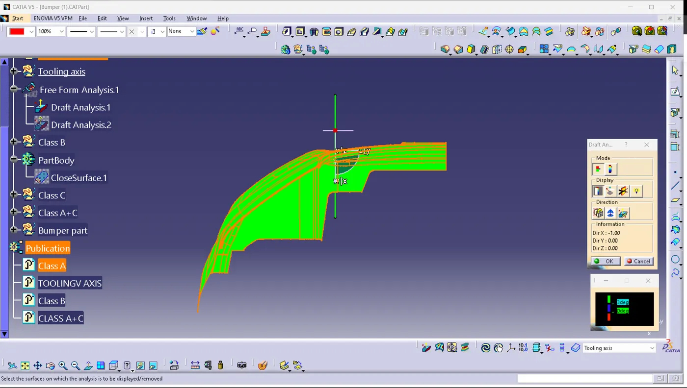
A cross mark will appear when you move the mouse curser over the surface. Click on the surface and lock it.
Class A SURFACE:
Plastic component: