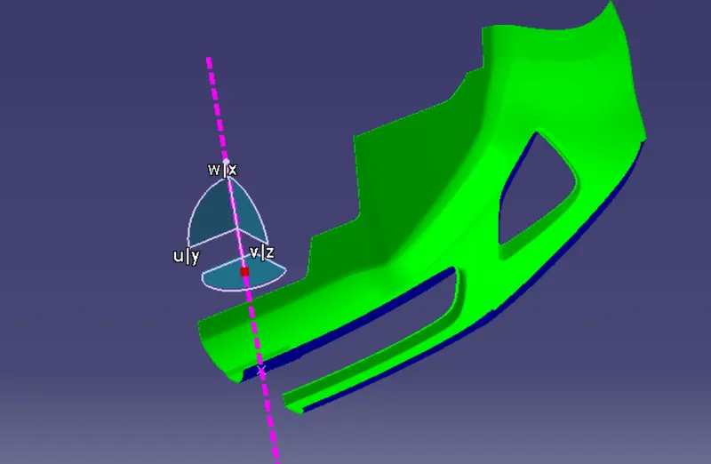
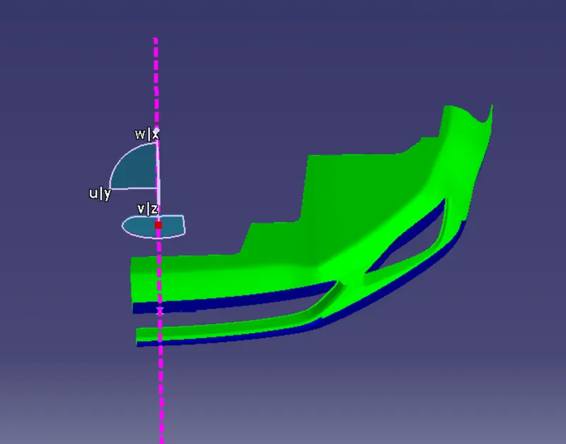
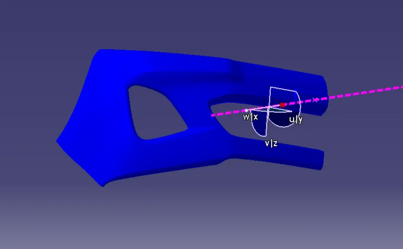
Week 9 - Challenge 3 - Bumper
STEP 1: The connectivity of the Class A Surface was checked using the JOIN command.
STEP 2: The tooling axis was created by drawing a perpendicular to the flat surface of Class A.
STEP 3: Draft analysis was done about the tooling axis.
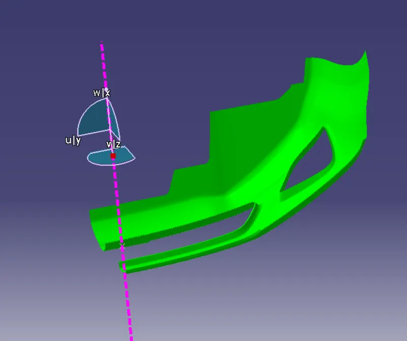
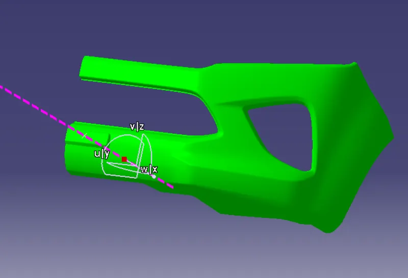
This tooling axis was giving appropriate results.
Step 4: An offset of class A was made by selecting the entire Class A using the offset command with an offset value of 2.5. And a lot of surface repairs were made to fix the offset made. This is now Class B.
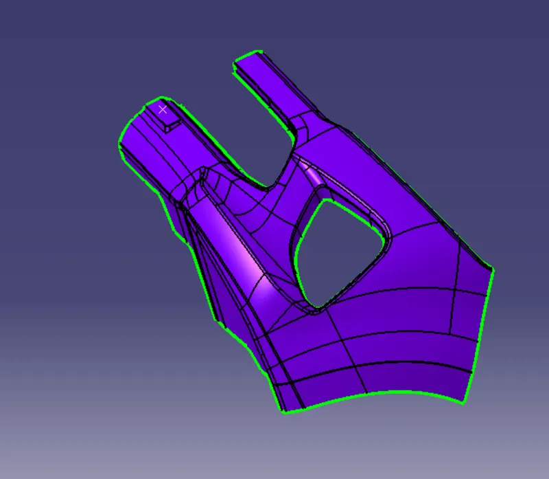
Step 5: A boundary of Class A was made and then then it was swept at 3 degrees along the draft direction using the SWEEP command and WITH DRAFT DIRECTION. This is class C.
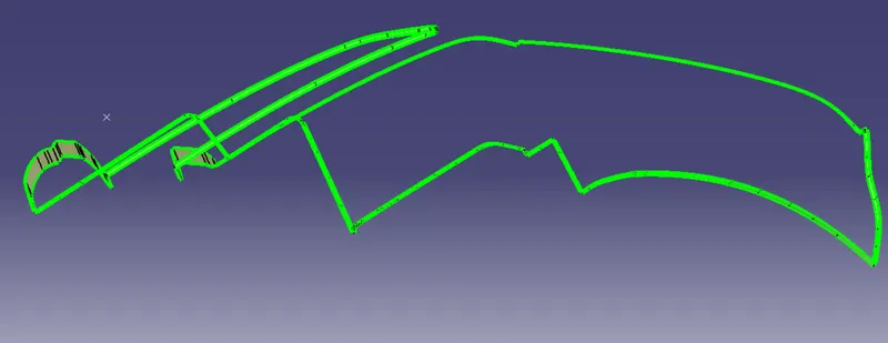
Step 6: Then Class A and Class C were joined.
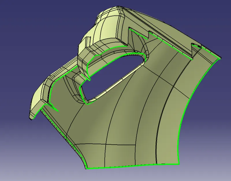
Step 7: Then Class A+C was trimmed with Class B. This is the final trim.
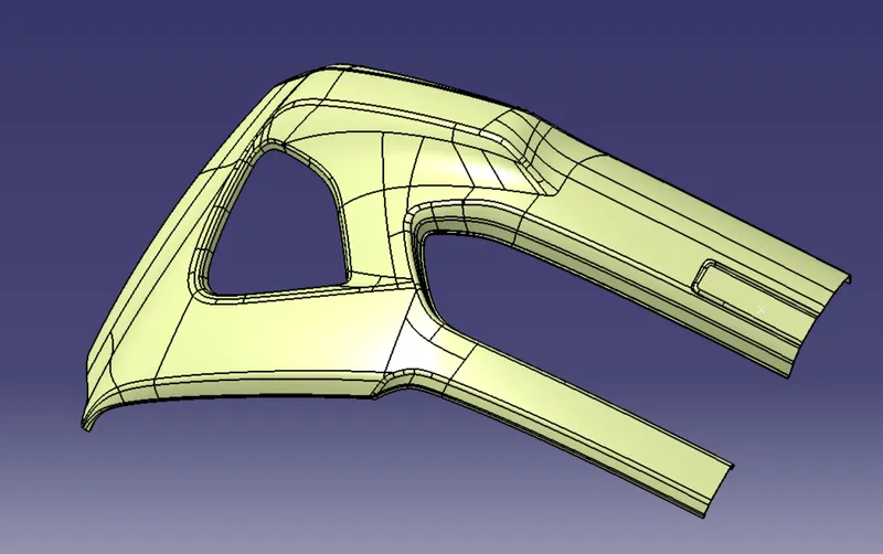
Step 8: The surface was made into a solid using the Close Surface command in the mechanical part design workbench.
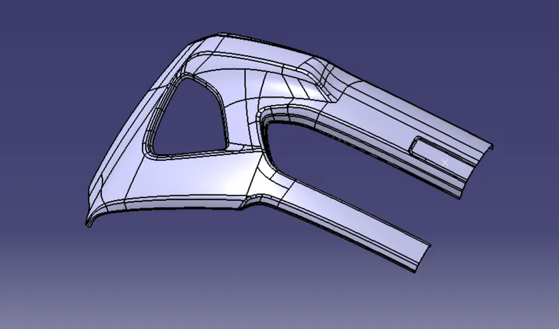
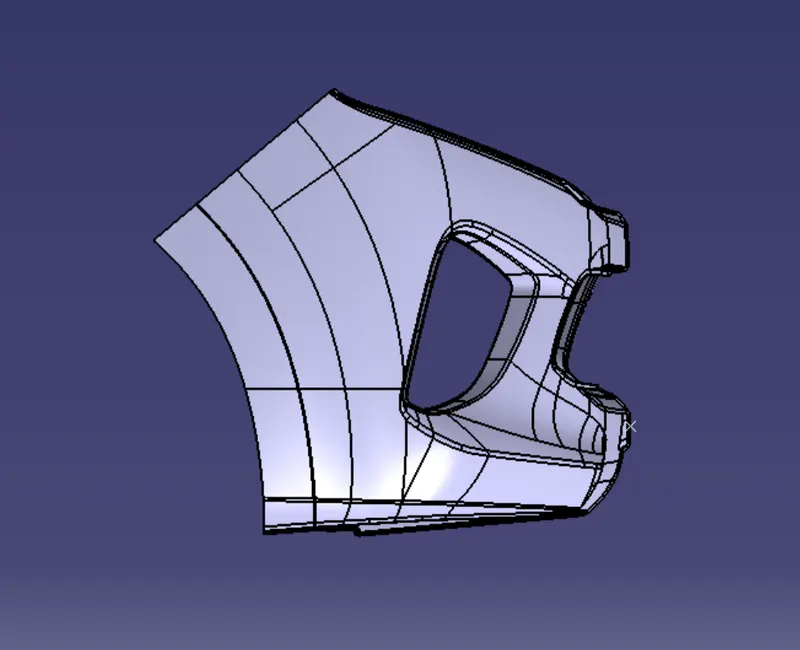
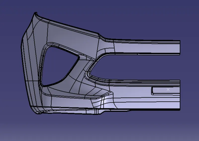
Step 9 : Again draft was analyzed.