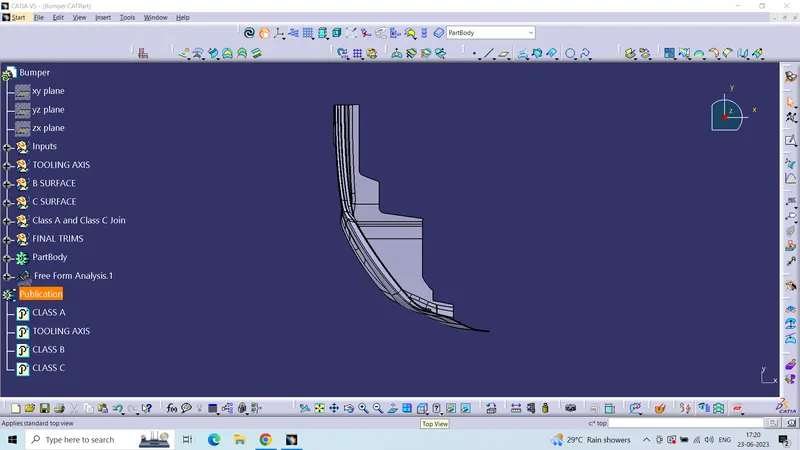
Week 9 - Challenge 3 - Bumper
AIM : Create the Bumper Plastic component through the given Class-A surface. To begin with, the tooling axis for the given Class-A Surface should be created meeting the requirements of the draft angle and at the end perform the Draft analysis on the model.
REPORT ON DRAFT ANALYSIS:
Given Class A Surface: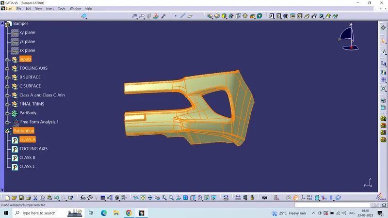
STEP 1 : To check the connectivity of CLASS - A surface by ensuring there is no gap between the component by using Join or Boundary Command. Design check is completed.
STEP 2 : Find the tooling axis of the component. The tooling axis is the axis from which mold opens and closes or the cavity opens and closes.
STEP 3 : CREATION OF TOOLING AXIS
- Check the best tooling direction for the given surface.
- We can find out the best tooling direction by cross checking all the three axes.
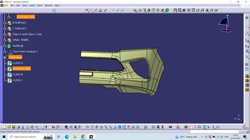
- Here we can find out that the best tooling direction for the bumper class-A surface is along x-axis direction.
- To create the tooling axis first place a point on midpoint of the surface.
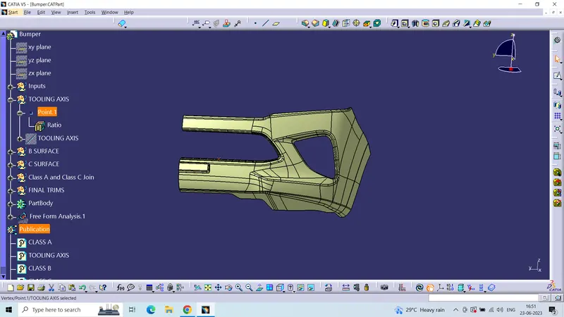
- Now create a line along the placed point and extend upto the desire length. Therefore the main tooling axis is created and published
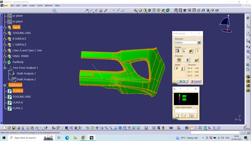
STEP 4 : DRAFT ANALYSIS OF CLASS A SURFACE:
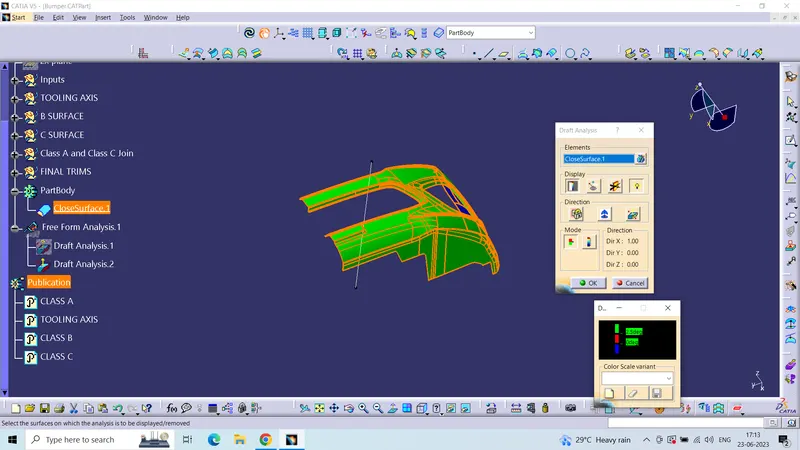
- Now perform the Draft analysis using the Featured Draft Analysis tool in the tools. Before performing the draft analysis ensure the surface should be in material mode.
- Open the draft analysis toolbox and select the compass and try to align W-Component with the main tooling axis and later click on the lock symbol after aligning.
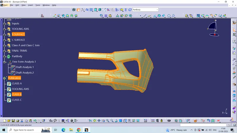
CREATION OF CLASS B SURFACE (B SURFACE):
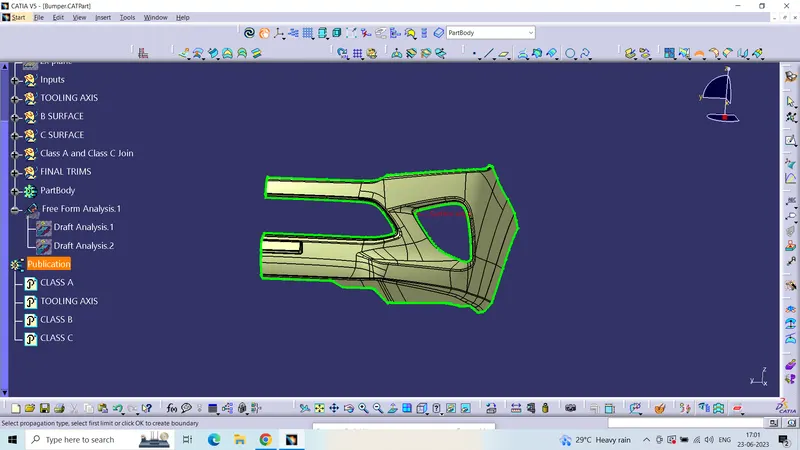
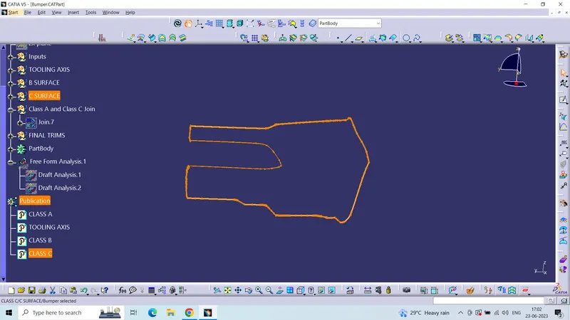
CREATION OF CLASS C SURACE (C SURFACE) :
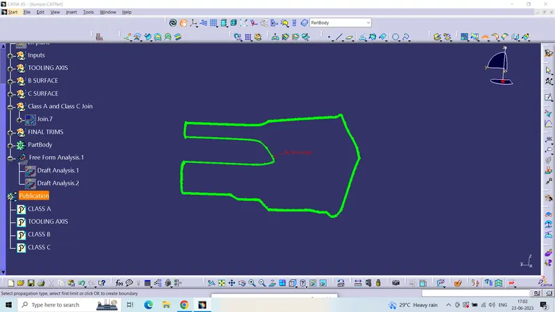
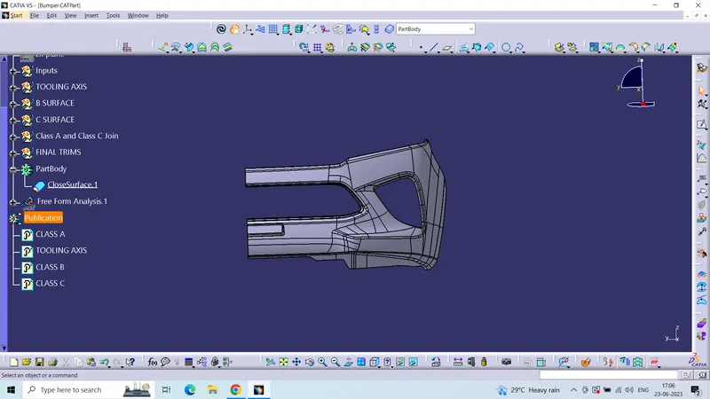
FINAL PLASTIC COMPONENT:
DRAFT ANALYSIS OF FINAL PLASTIC COMPONENT:
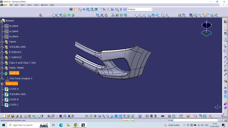
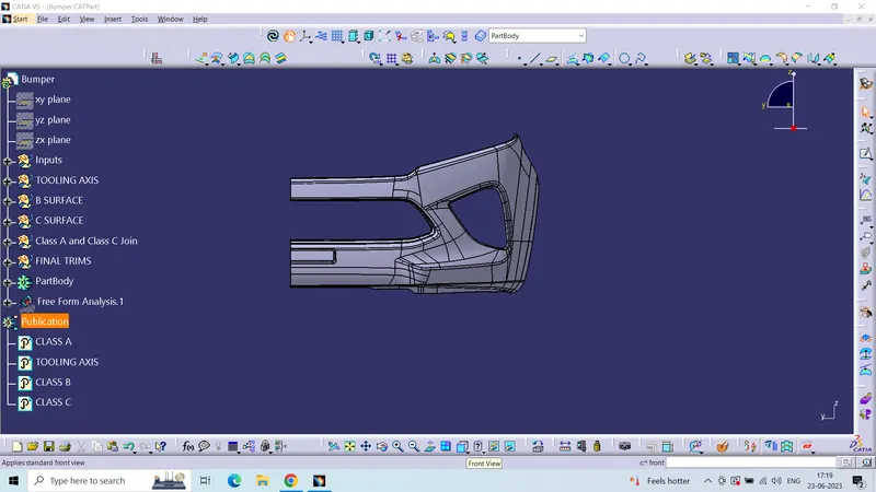
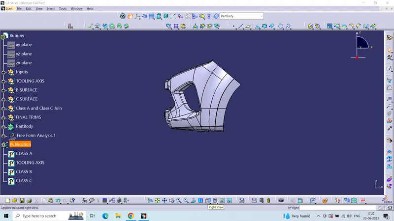
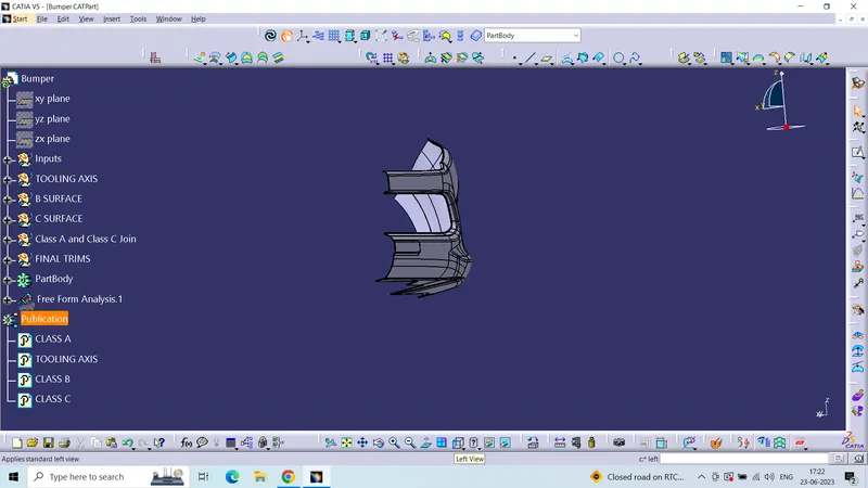
The FOLLOWING ARE THE 3D PART MODEL IN VARIOUS ORIENTATIONS IMAGES.