Week 9 - Challenge 3 - Bumper
CREATION OF TOOLING AXIS:
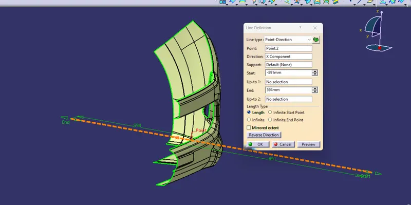
Tooling axis is the direction in which a core or cavity of mold opens. This Axis is very important to determine the orientation of the component in mold, core and cavity design.
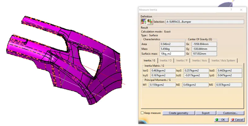
The tooling axis is created by the inertia method by using the steps as follow
-
Click “Measure inertia” and select the A-surface
-
Click “Create geometry” in the Measure Inertia window.
-
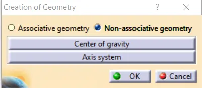
In the Creation of Geometry window, select Non-associative geometry.
-
Click “Center of Gravity”
-
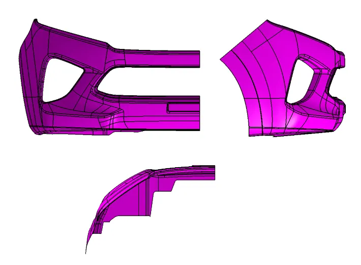
The component is viewed in all axes namely X,Y and Z.
-
It is determined that the X-axis will be the direction for the Tooling axis and a line is created Using the CG point and X-direction as direction of the line.
-
-
DRAFT ANALYSIS OF A SURFACE:
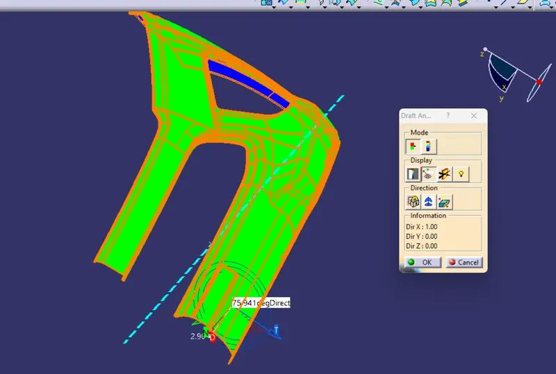
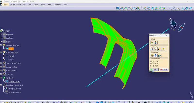
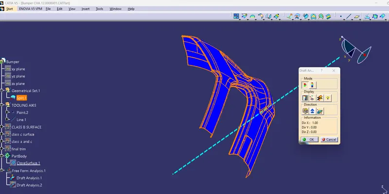
Draft analysis of the surface is carried to check if the surface or part can be manufactured with the required draft angle.
Draft angle is needed for the component to clear the core and cavity surface as it would have shrunk towards the center while cooling.
The draft angle in this design is 3 degrees. As A surface is a single surface there won't be much difference in color. The draft analysis of A-surface is shown below.
CREATION OF B-SURFACE :
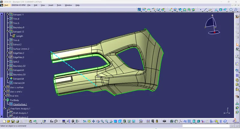
The A-surface is offsetted by 3.00mm as it is the thickness required.
CREATION OF C-SURFACE :
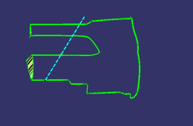
The A and B surfaces are connected by another single surface which is called the C surface.
CREATION OF CLOSED BODY :
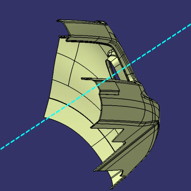
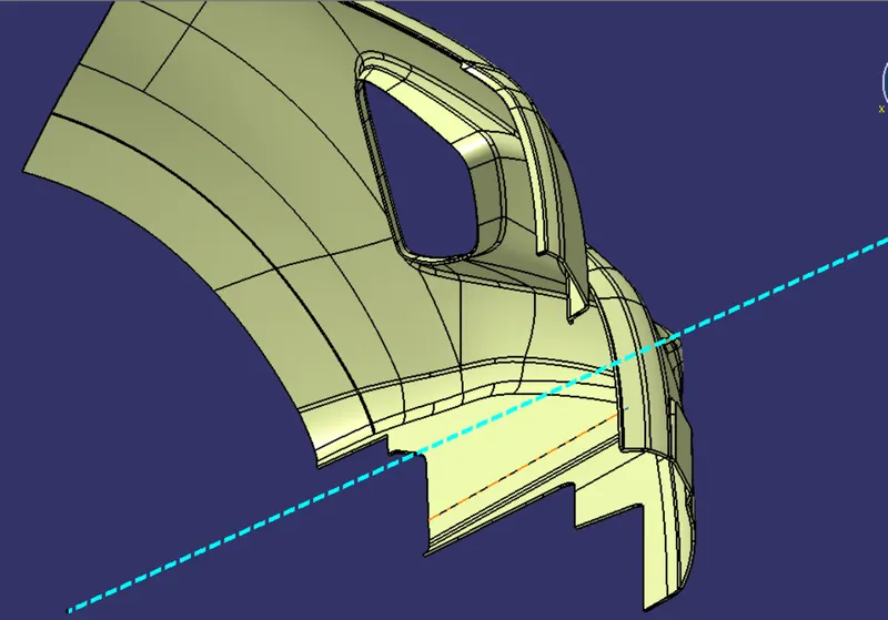
All the surfaces (A,B,C) are joined together to form a closed body.
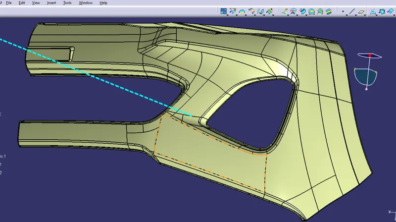
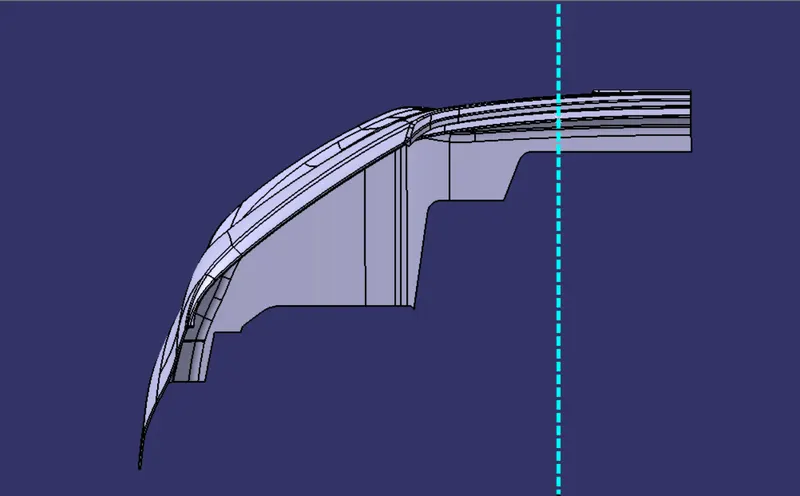
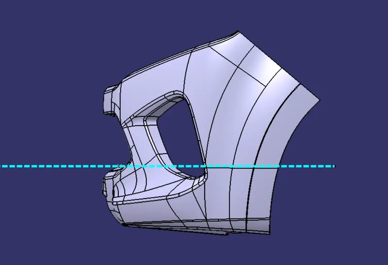
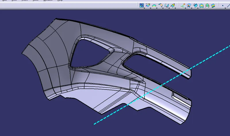
SOLID BODY
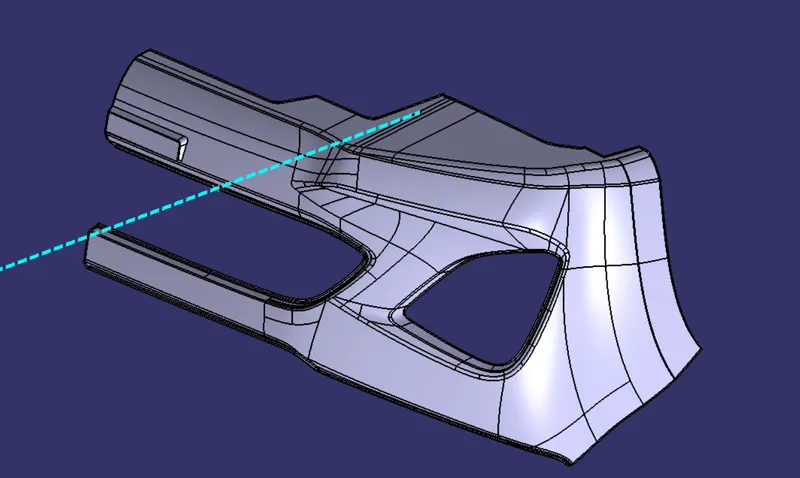
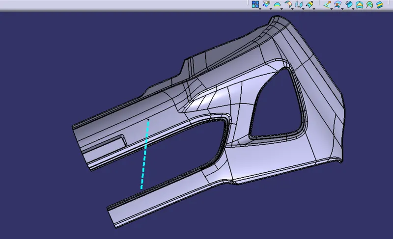
FROUNT VIEW:-
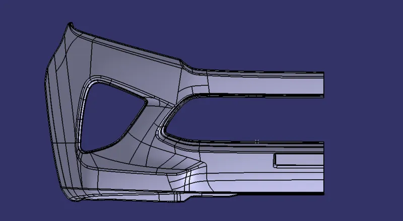
TOP VIEW;-
SIDE VIEWS:-

ISOMETRIC VIEW:-
MODEL TREE:
The model tree created shows that all the geometrical sets are named for clarity.

DRAFT ANALYSIS OF PART BODY:
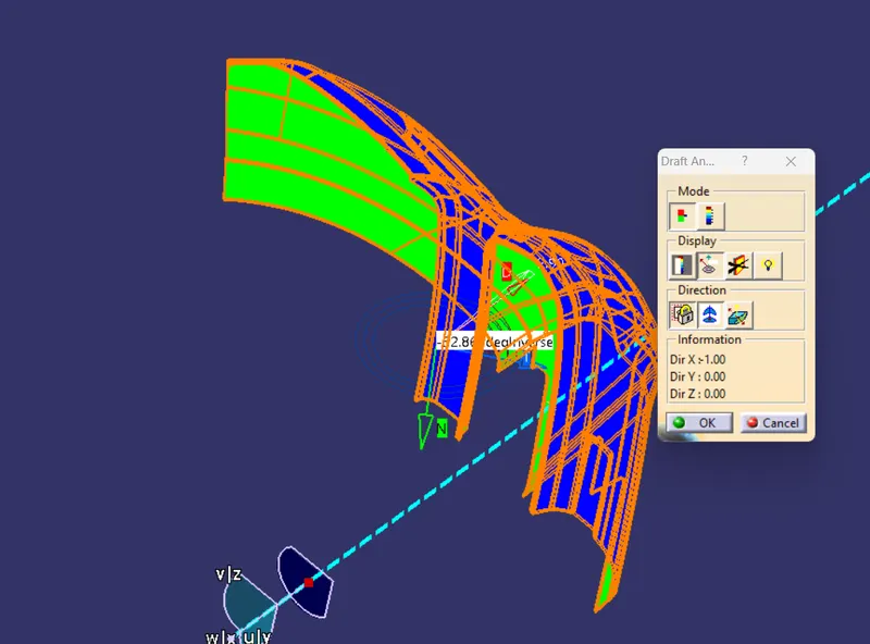
The final solid part body has to be analyzed using Draft analysis. This is done to check if all the areas of the body are satisfying the draft angle which is 3 degrees.
A draft angle is a taper applied to the vertical walls of the injection-molded component to assist with releasing the part from the mold.
Draft angles are a required feature of injection-molded custom parts. A functional part for injection molding has to have draft angles that face both the cavity and core sides. This will reduce the risk of damage to the parts and ensure that they can be ejected from the machine.