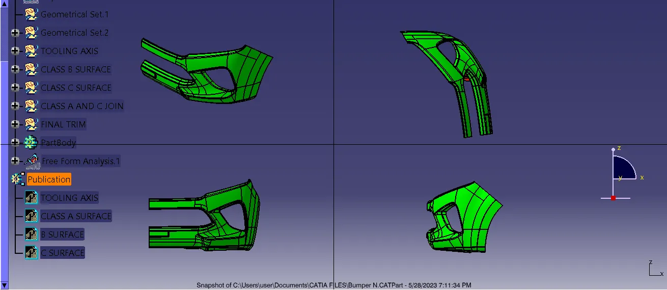
Week 9 - Challenge 3 - Bumper
Tooling Axis Creation-
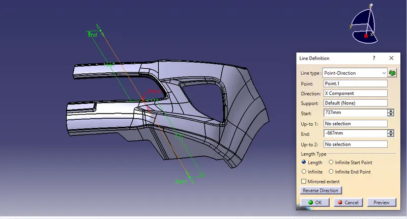
To create the tooling axis first, we have to check the best suitable direction for tooling by using the compass. the x direction is suitable for creating the tolling axis because, in the x direction, most of the surfaces are clearing while performing draft analysis. Generally tooling axis is created using bisecting line method but here A line normal to the surface is created in the x direction and considered the tooling axis.
Draft Analysis Class A Surface-
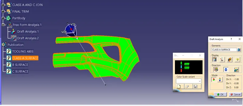
- Draft analysis is done after determining the tooling axis. It is used to check whether the minimum draft of 3 degrees is maintained or not.
- INSERT > ANALYSIS> FEATURE DRAFT ANALYSIS
- View mode is changed to custom view parameters- Material mode. then the Feature draft analysis is enabled.
- A compass is used to define the draft direction and it is locked on the tooling axis. By dragging the red pointer, Analysis under the running points in Display is selected.
Draft Analysis of Plastic Component-
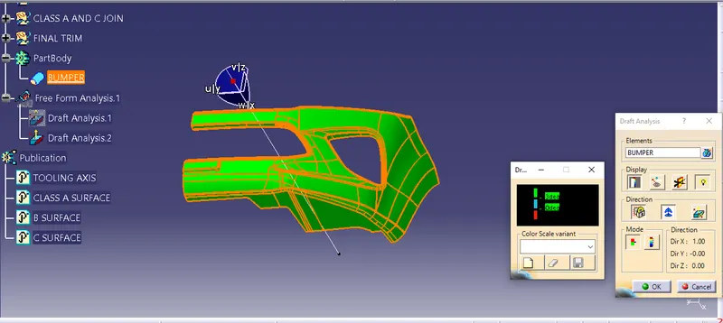
The green colour area shows that it satisfies the 3-degree draft angle (The blue colour area shows 0 to 3 degrees and the red colour area shows a negative draft angle). If not satisfied then by using the running point tool, the area is measured and then altered to get an appropriate draft for the created tooling direction.
Different views of the solid model-