Week 9 - Challenge 3 - Bumper
DESIGN AND DRAFT ANALYSIS OF A CAR BUMPER
Aim -
Create the Bumper Plastic component from the given Class A surface and perform a draft analysis on it. Take the thickness of the component to be 3mm.
Design Methodology -
- Check the given Class A surface for any discontinuity.
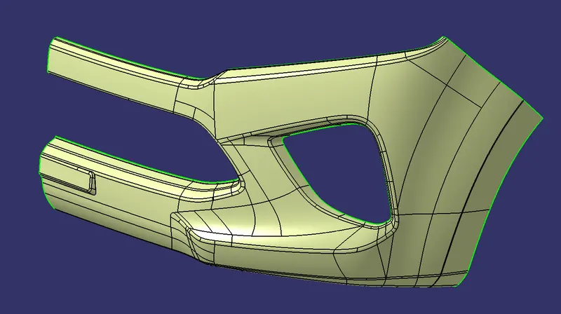
- Determine the Tooling Axis of the part.
- Start by checking the surfaces draft through each axis of the component.
- Select the axis which shows most of the surface and it’s sides clearly while performing a draft analysis.
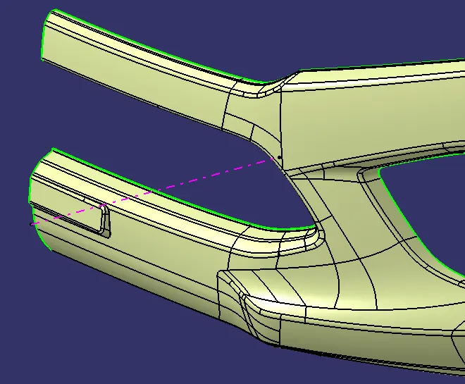
- Create a point approximately on the flat surface perpendicular to X axis.
- Create a line parallel to X axis passing through that point. This is the reference tooling axis
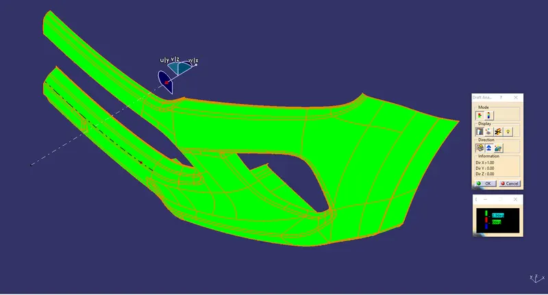
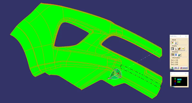
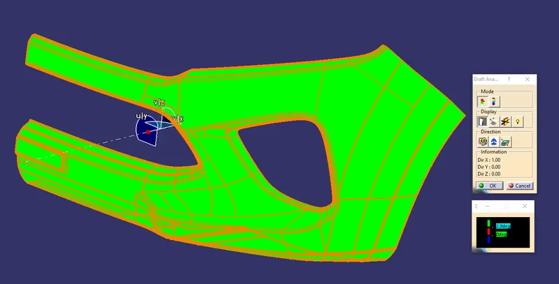
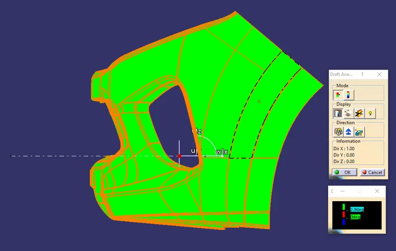
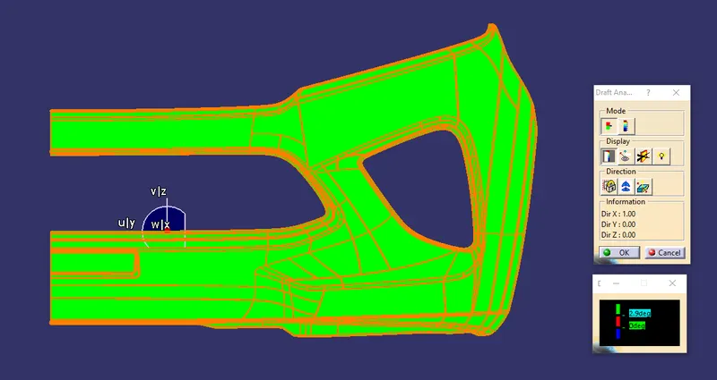
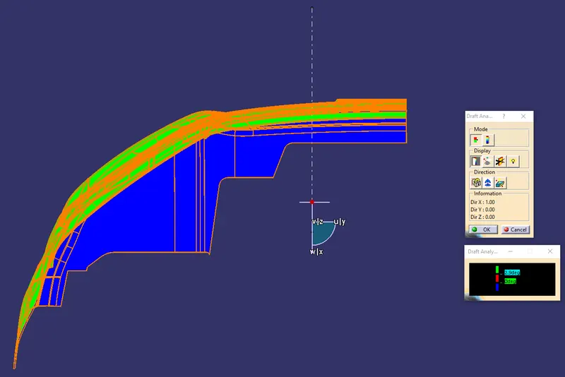
- Do a Draft analysis of the Class A surface with the reference tooling axis as the draft axis.
- If the part passes the draft analysis, the reference axis can be finalized as the main Tooling Axis.
- Create the Class B Surface.
- Offset the Class A surface inwards by 3mm to account for the thickness of the part.
- Check the Offsetted surface for discontinuities.
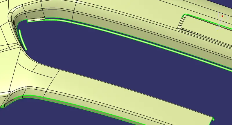
- Make patches for the discontinuous surface. Here, we needed three patches :
At the top part of the Bumper.
At the grill of the Bumper.
At the number plate positioning emboss.
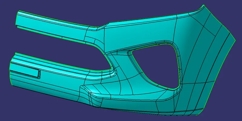
- Add edge blends to the patched surfaces.
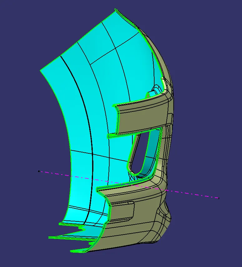
- Create the Class C Surface.
- Extract the surfaces boundaries which are parallel and perpendicular to the draft tooling axis using multiple extract.
- Create Swept surfaces to the boundaries :
90deg to the surface and inwards for the parallel surface’s boundaries.
3deg With respect to the draft for the perpendicular surface’s boundaries.
- Join all the swept boundaries to form the Class C surface.
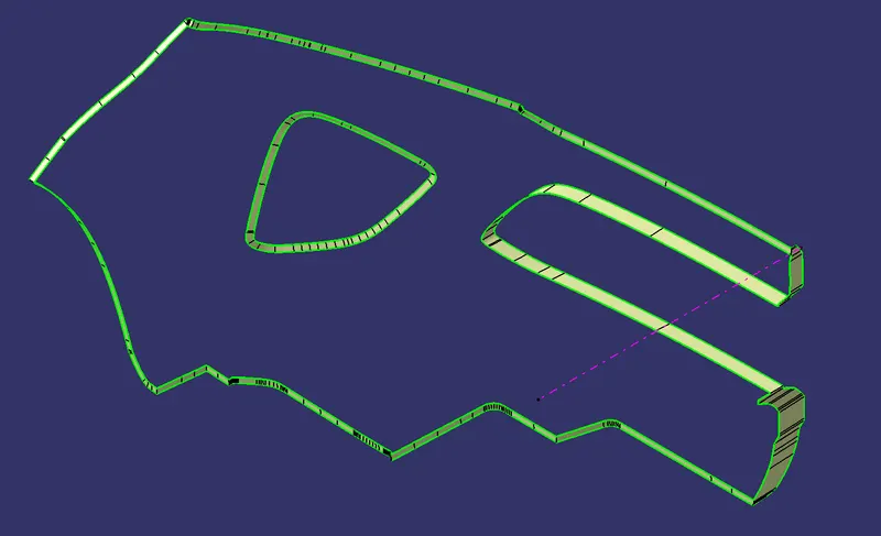
- Join the Class A surface and the Class C surface.
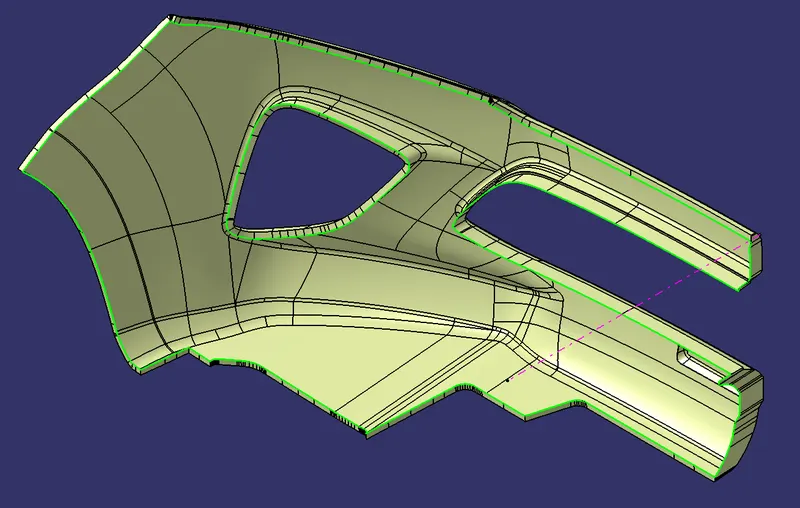
- Extrapolate the Class B surface so that the above mentioned joined surface intersects completely with it.
- Trim the Class B surface with the joined surface to get the closed hollow surface of the component.
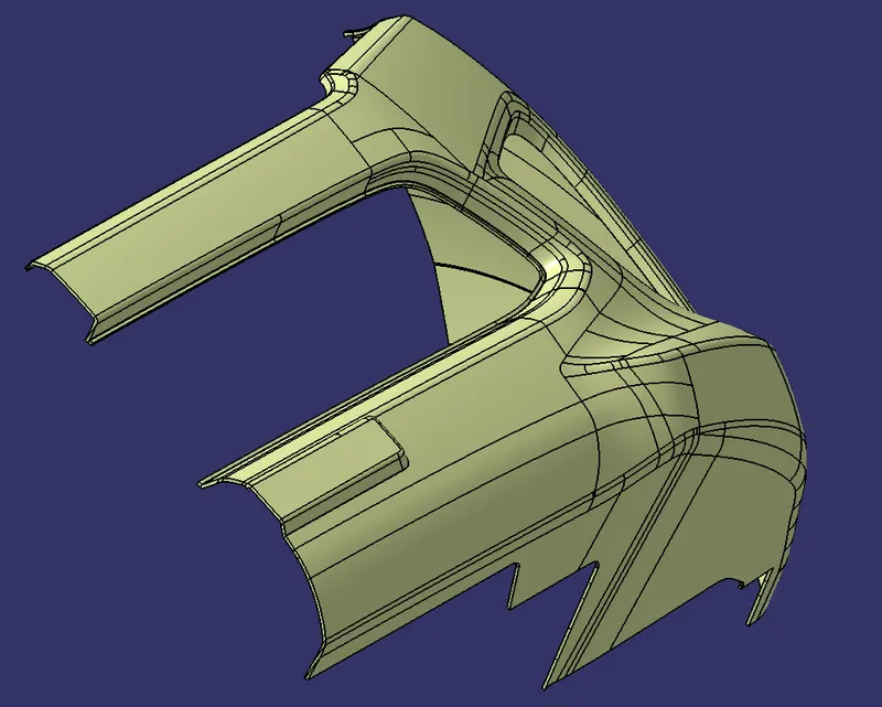
- Use the closed surface command in part workbench to produce the final Solid part.
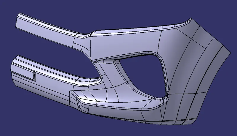
Isometric View -
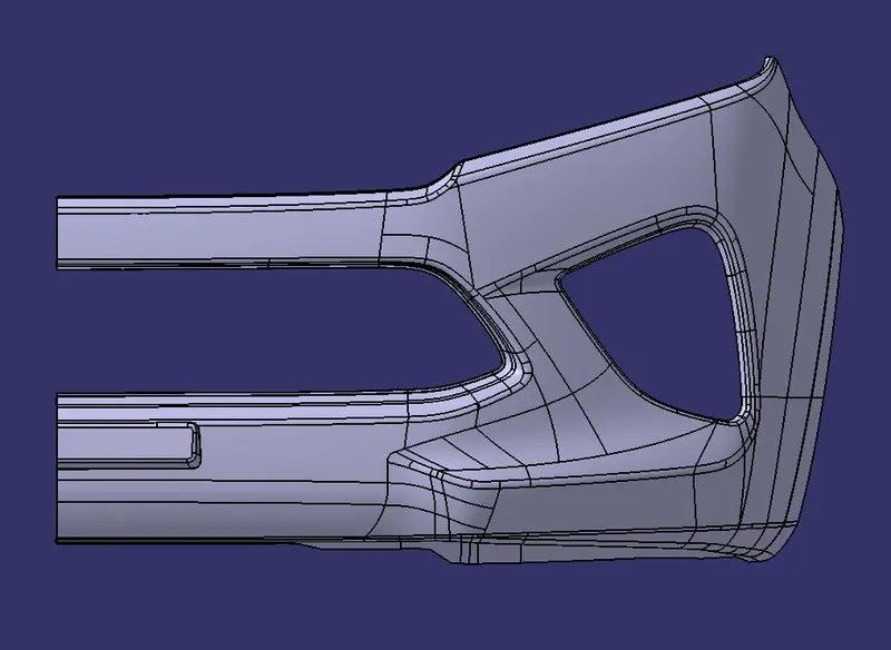
Front View -
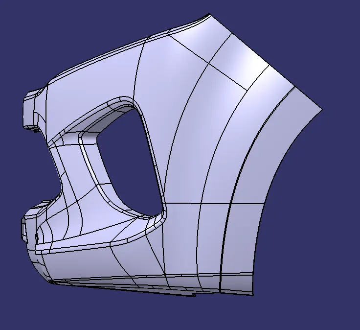
Side View -
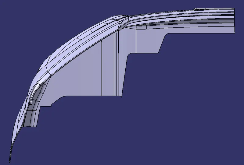
Top View -
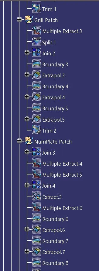
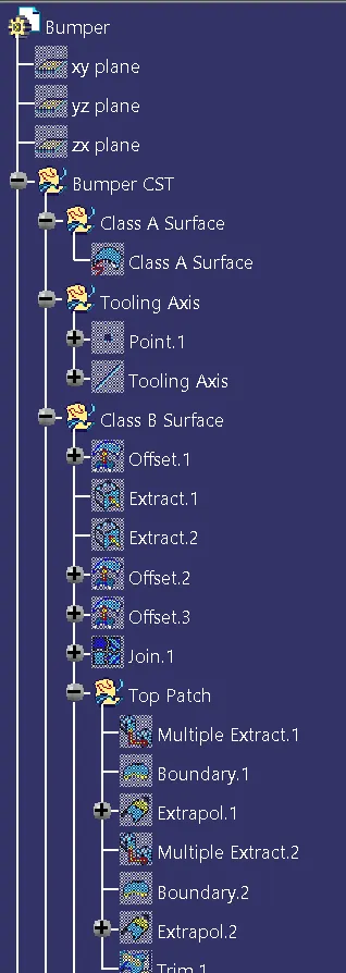
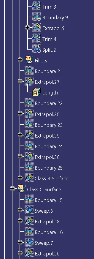
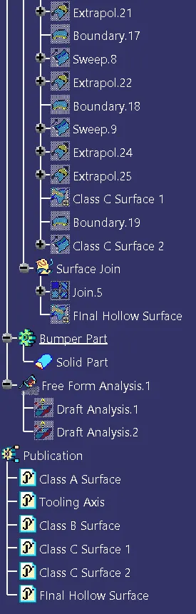
Tree Structure of the design process -
Draft Analysis of the surfaces -
Class A Surface :
Final Solid part body :
Isometric View -
Side View -
Front View -
Top View -
Result and Conclusion -
- The desired part is produced by taking the draft requirements and thickness into consideration.
- Draft analysis is conducted on the Class A surface and the final solid part has a positive result.