Week 9 - Challenge 3 - Bumper
Aim-
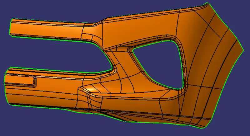
Create the Bumper Plastic component through the given Class-A surface. To begin with, the tooling axis for the given Class-A Surface should be created meeting the requirements of the draft angle and at the end perform the Draft analysis on the model.
REPORT
BUMPER
A bumper is a structure attached to or integrated with the front and rear ends of a motor vehicle, to absorb impact in a minor collision, ideally minimizing repair costs.Stiff metal bumpers appeared on automobiles as early as 1904 that had a mainly ornamental function. Numerous developments, improvements in materials and technologies, as well as greater focus on functionality for protecting vehicle components and improving safety have changed bumpers over the years. Bumpers ideally minimize height mismatches between vehicles and protect pedestrian frominjury. Regulatory measures have been enacted to reduce vehicle repair costs and, more recently, impact on pedestrians.
CLASS A SURFACE
In automotive design, a class A surface is any of a set of free form surfaces of high efficiency and quality. It gives the aesthetic of the component which is created by the styling team and gives to the part design engineer to create the part with all engineering aspects.
CREATING THE CLASS A SURFACE
We have been given the Class-A surface and the first thing to do is to make sure that the given surface has no gap in between them. We can check it visually and also with help of Join or boundary commands.
TOOLING AXIS
The direction in which the mold or core and cavity opens is the tooling axis.
By checking the all three axis the best tooling direction is determined. flat surface or bin area is choosen for creating dummy tooling axis
created point on extracted base surface and a perpendicular line is drawn and Dummy tooling axis created
TOOLING AXIS USING BISECTING METHOD
Tooling axis for the part is created by using the bisectiong method .In order to check whether the part is toolable in the direction,the class A surface is analysed and the walls which are doubtful of clearing the 3 degree draft angle to the dummy tooling axis is identified.
an axis system is created on point to take intersection on both axis
lines are drawn atthe walls which are almost parallel to dummy tooling axis
bisecting lines are drawn to these two lines and first bisecting line is created
similiarly second bisecting line is created using the intersection onthe second axis
TOOLING AXIS is created by bisecting the axis created on two intersections .
TOOLING AXIS FOR BUMPER
the best tooling direction for the class-A surface is along x-axis direction.
Flat surface on the center part of the bumper is extracted for creating the tooling axis in x direction
Then created a with the point and direction along x axis.
TOOLING AXIS of the part is created
DRAFT ANGLE
When developing parts for plastic injection molding, applying a draft (or a taper) to the faces of the part is critical to improving the moldability of your part. Without it, parts run the risk of poor cosmetic finishes and may bend, break, or warp due to molding stresses caused by plastic cooling. Equally important, an absence of draft may prevent parts from ejecting from the mold, damaging not only the parts but possibly the mold itself—a costly and time-consuming detour.