Week 9 - Challenge 3 - Bumper
Week 9 - Challenge 3 - Bumper
BUMPER SURFACE DESIGN :-
It is Given that Create the Bumper Plastic component through the given Class-A surface. To begin with, the tooling axis for the given Class-A Surface should be created meeting the requirements of the draft angle and at the end perform the Draft analysis on the model. Take the Thickness of the component to be 3 mm
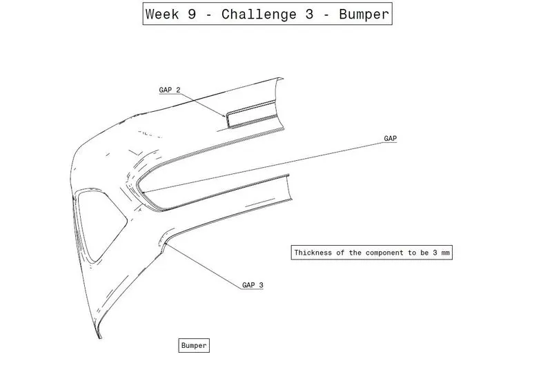
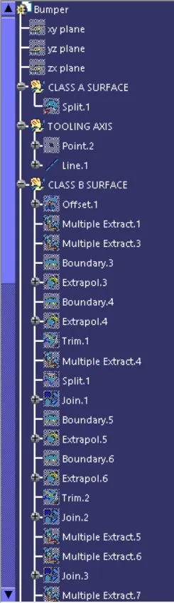
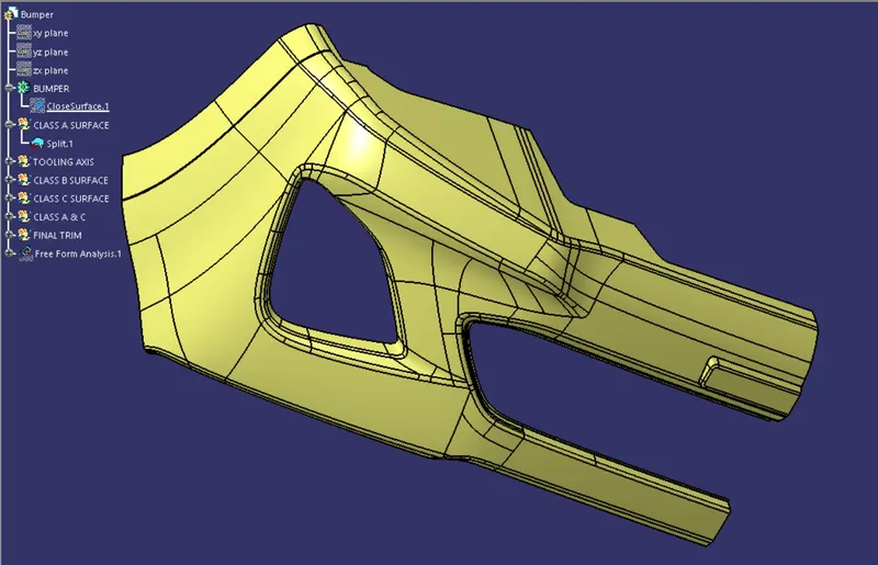
Given Class A surface is shown in below image.As in Requirement is told that 3mm thickness should be of Solid Component. For that we have design Class B & Class C surface.
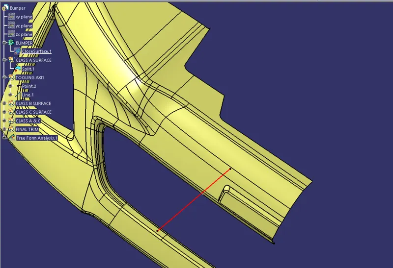
Start With the Tooling axis For the Class B Surface,For the tooling we can start with the curve portion where we can draw a perpendicular axis.Get edge select create point on that in middle and draw a line on it, for checking the tooling axis is on correct surface get the draft anyalais and place compass on it and if the part ge tin green color then tooling axis is correct.
after creating tooling axis start with Class B surface first take the offset of the whole give class A surface and offset it for 3mm as given.
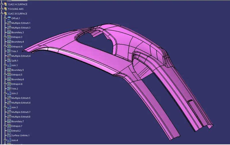
But taking offset direct then patch/gaps get created as shown in the image.
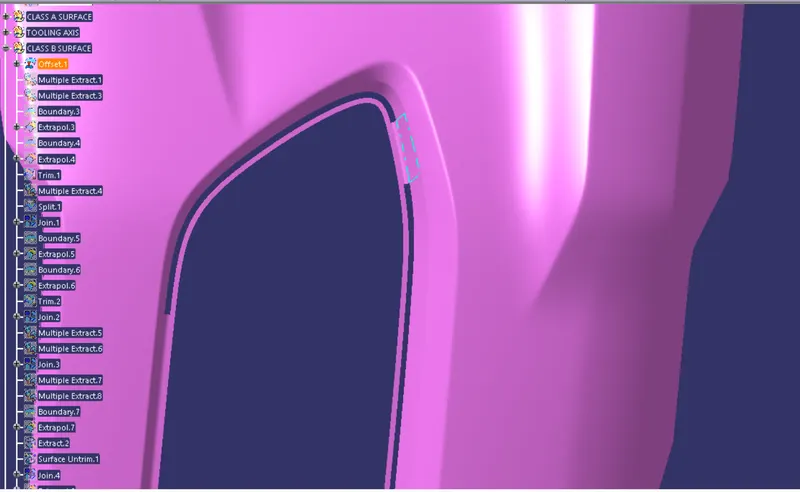
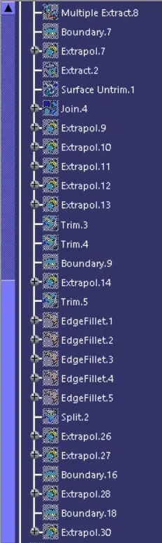
for getting this Patchs fill use different steps/procedure.As shown in the fig the spilt and extract command step is used to fill patch and after extrapolate in proper directions Gap is covered.
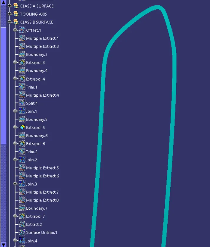
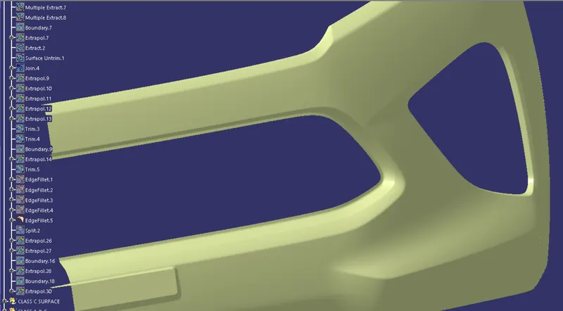
After getting all patch filled and Trimming.Edge Fillet should be done and your Class B is Created.
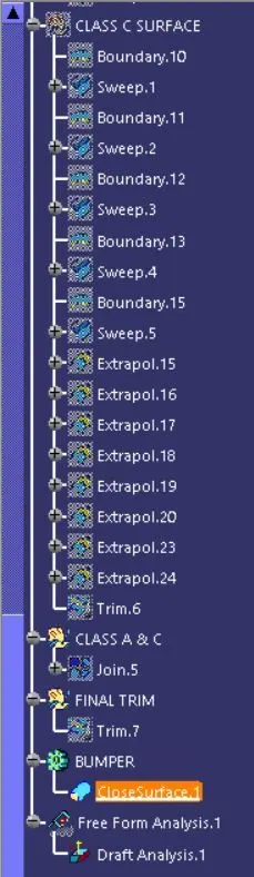
Now for the Class C surface use boundary nad the etrapolater command and proper length that wil get intersect each other And to get proper Sweep.
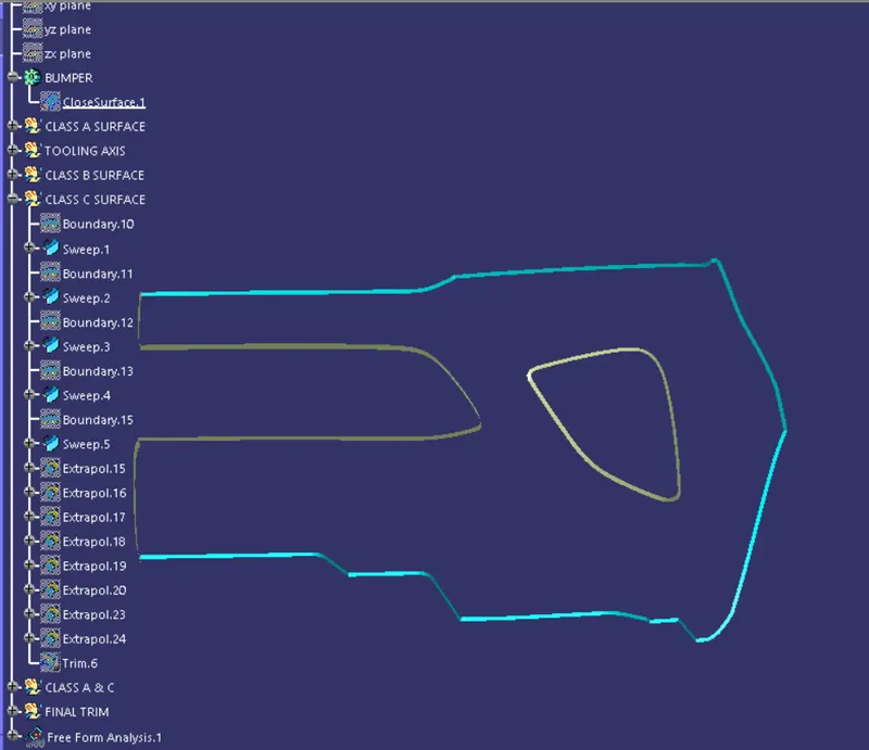
Join Class A and Class C to check for proper thickness and Error in thickness.
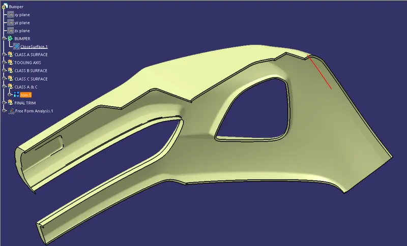
for the final part thickness of 3mm just trim Class B with joined Class A&C.you get final part which can be turn to solid.
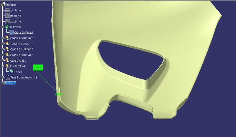
Solid 3mm thickness part used Closed Surface command from Part Drawing.
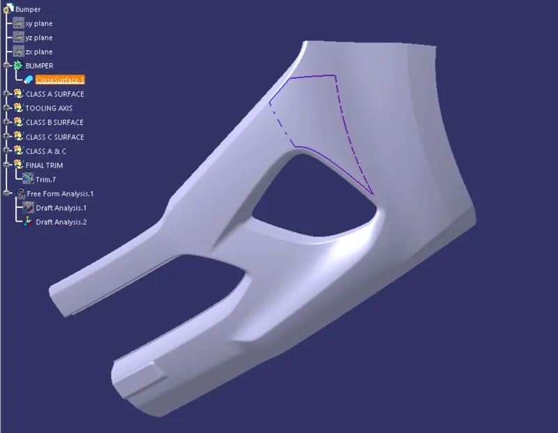
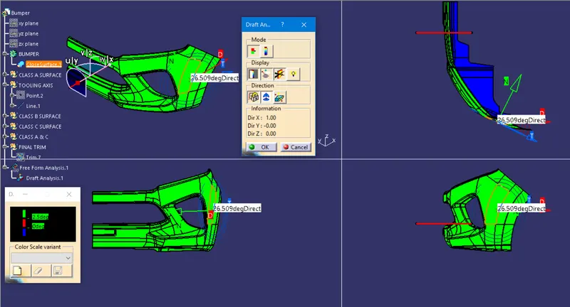
Draft Analysis of the Created solid Part.
Click draft analysis after that change view mode to customize view and select material now in draft analysis dialoge box click compass then pic compass put it on the tooling axis and lock the compass now select the marker and drat analysis symbol in dialogue box.check for futher requirements.
The Class C created sweeps were of 3 degree the draft analysis use to show in red then the scale was drop down to 2.5 degree now the whole part is in green color as shown in the image.
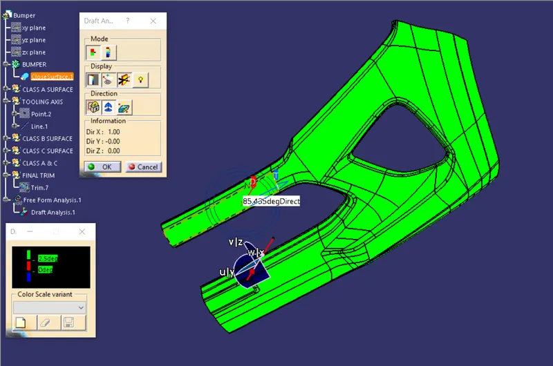
below fig shows Class A surface Draft analysis in iso,top,side,front.
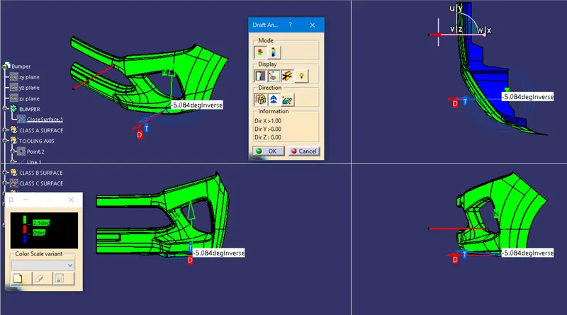
below fig shows closed surface surface Draft analysis in iso,top,side,front