Week 9 Challenge
Aim:- Our Aim is that to calculate the scour depth and fix the span for given liner waterway and find out the suitable foundation for the abutment and pier,Calculate the forces as per IRC 6 on the foundation and propose the foundation ,Define the Liquefaction and its effects how it can affect foundation. Also list the remedial measures for the same And How it is different from scouring.
Introduction:-
Pier and abutment underming due to scouring and riverbed erosion has been widely recognized as the main cause of bridge damage and faliure. The federal Highway Administration (FHWA)has estimated that 60% of bridge collapses are due to scour . The Phenomenon of local scour has been extensively studied at bridge piers and abutment founded in non- Cohesive sediments.
Procedure:-
Given Data
1. A river of linear waterway = 90 m
2. Design discharge = 700 cumec
3. Silt factor = 1
4. Velocity of water = 1.2m/sec
5. Top road level=100 m
6. Ground level= 93.5 m
7. Vertical pile capacity for 1.2 m dia is 250 tonnes
8. Horizontal pile capacity for 1.2 m dia is 35 tonnes
9. Well having 8 m diameter capacity 70 tonnes/m2
10. Well having 6 m diameter 50 tonnes/m2
11. Well having 7 m diameter 60 tonnes/m2
Calculation
dsm=1.34(D^2/K)^(1/3)
For Abutment
D=1.3Q/L
=1.3*700/90
=10.11 m3/sec/meter width
dsm=1.34(10.11^2/1)^(1/3)=6.265 m
dsm,abutment =1.27 *dsm
=1.27*6.265
=7.97 m
Depth of Foundation below ground level=7.97-3
=4.97 m
For Pier
D= 1.3Q/L
=1.3*700/90
10.11 m3/sec/meter width
dsm =1.34(D^2/K)^(1/3)
=1.34(10.11^2/1)^(1/3)
=6.265 m
dsm abutment =2*dsm
=2*6.265
=12.53 m
Depth of foundation below ground level =12.53-3
=9.53 m
Calculate the forces as per IRC 6 on the foundation:-
Load % to be taken after Reduction (in case of three lanes)=90%(Cl.205,IRC 6 2014)
Fraction of live load remaining in seismic case = 0.2
1 Lane 70R-Wheeled
Load =98.0665 t
1 Lane Class A
Load=42.3648 t
Load % to be taken after Reduction (in case of three lanes)=90%(Cl.205,IRC 6 2014)
Fraction of live load remaining in seismic case = 0.2
1. 1 Lane Load Reactions
Ra=98.1*(15-4.4-0.5-.05)/14=67.269 t
Rb=98.1-67.269
=30.831 t
vertical reaction on abutment =67.269 t
Braking force=20%of98.1 t
=19.62 t
Change in Reaction due to braking force= 4 t
Maximum Vertical force on abutment =67.268 t
Minimum Vertical force on abutment =57.8 t
Longitudinal Moment = 0 t-m
Total Horizontal force at bearing level =Fh/2
=15.6/2=9.8 t
Total horizontal force (Longitudinal )HL=9.8 t
Total horizontal force (Transverse)HT=o t
Eccentricity =0.855 m
Transverse Moment MT =56.259 t-m
2. 1 Lane Class A:-
Ra=42.4*(15-3-0.5-.05)/14=33.32 t
Rb=42.4-33.32
=9.08 t
vertical reaction on abutment =32.32 t
Braking force=20%of42.4 t
=8.47 t
Change in Reaction due to braking force =1.7 t
Maximum Vertical force on abutment =32.32 t
Minimum Vertical force on abutment = 27 t
Longitudinal Momentn= 0 t-m
Total Horizontal force at bearing level =Fh/2
=8.4/2=4.2 t
Total horizontal force (Longitudinal )HL= 4.2 t
Total horizontal force (Transverse)HT =0 t
Eccentricity =2.45 m
Transverse Moment MT =103.88 t-m
3. 2 Lane Class A:-
Ra=2*42.4(15-3-0.5-.05)/14=66.64 t
Rb=2*(42.4-33.32)
=18.6 t t
vertical reaction on abutment =66.64 t
Braking force=20%of 84.8 t
=16.96 t
Change in Reaction due to braking force =3.4 t
Maximum Vertical force on abutment =66.64 t
Minimum Vertical force on abutment =27 t
Longitudinal Moment =0 t-m
Total Horizontal force at bearing level =Fh/2
=16.8/2=8.4 t
Total horizontal force (Longitudinal )HL =8.4 t
Total horizontal force (Transverse)HT = 0 t-m
Eccentricity 2.45 m
Transverse Moment MT =207.76 t-m
Zero Shear Point:-
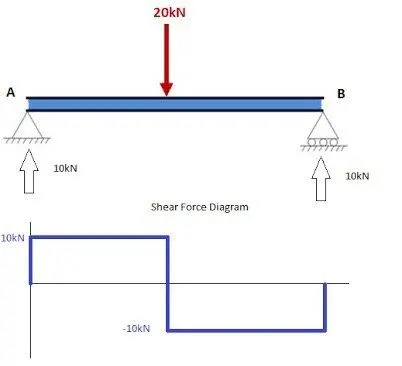
The shear force diagram is sloping between A and C and the point aof zero shear force occurs at B, the centre point. At support C the reaction of 30kN brings the value of shear force back to zero and the diagram is complete.
The Point in a member at which B.M. is zero , are called point of contraflexure or inflexion.The point at which we get zero shear force,we get the maximum bending moment of that section /beam at that point.
The maximum bending moment:-
The maximum bending moment occurs in a beam, when the shear force at that section is zero or changes the sign because, at point of contra flexure the bending moment is zero. Explanation: The positive bending moment in a section is considered because it causes convexity downwards.
For Exmaple
Liquefaction:-
Liquefaction is a phenomenon in which the strength and stiffness of a soil is reduced by earthquake shaking or other rapid loading. Liquefaction and related phenomena have been responsible for tremendous amounts of damage in historical earthquakes around the world.
Liquefaction occurs in saturated soils, that is, soils in which the space between individual particles is completely filled with water. This water exerts a pressure on the soil particles that influences how tightly the particles themselves are pressed together. Prior to an earthquake, the water pressure is relatively low. However, earthquake shaking can cause the water pressure to increase to the point where the soil particles can readily move with respect to each other.
Liquefaction effects, how it can affect foundation:-
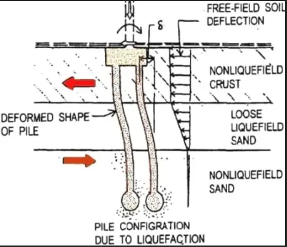
Pile foundations are likely to experience liquefaction and its effects on such foundation are in several forms or ways. Effects of liquefaction on pile foundation is discussed. Liquefaction is a phenomenon in which loose saturated soil such as loose sandy silts and loose sandy soils will strength substantially. There are tests such as standard penetration test and cone penetration test to specify whether a certain soil is expected to suffer from liquefaction or not.
Effect of Liquefaction on Pile Foundation:-
- Buckling of piles in liquefiable soil
- Lateral spreading of sloping ground
Buckling of Piles in Liquefiable Soil:-
Piles are considerably long element and the soil around it offers an excellent support. However, if the soil is soft and the supported load is large, then it is likely that the pile would buckle. It should be known that buckling of pile foundation is not common and the aforementioned conditions should be meet in order for the pile to suffer buckling. Pile foundation usually carries loads through skin friction and base capacity. The former is created by horizontal stress around the pile surface area. The horizontal stress would act similar to strut with smaller spacing and hence a lateral support is generated. When the soil around the pile foundation liquefied due to earthquake affects, then the loss of lateral support is highly probable and consequently skin friction would no longer occur. Based on the recommendation of Eurocode-8, the strength of liquefied soil should be ignored. So, buckling of pile foundation is very likely to occur when it supports large axial loads and loss its lateral support due to soil liquefaction. Pile foundation is anticipated to buckle if pile toe is fixed in a bedrock and the axial load supported by the pile is substantially large in comparison with Euler buckling load of an equivalent column. The Euler buckling load (PE) is computed according to the following expression.
Pcr = ( π2 EI ) / Le^2
Where: EI: pile flexural rigidity Le: pile equivalent length based on pile end conditions The pile is assumed to be vulnerable to buckling unless the computed design load is smaller than the Euler load by a factor of five. The Euler equation provided above may be utilized on the condition that the pile does not have imperfections and the load acts completely on the pile center. If such condition does not meet, the computed bucking load will considerably decrease. That is why large factor is provided between design load of the pile and Euler buckling load. Slenderness ratio, which is equal to equivalent length divided by radius of gyration, is another indicator by which potential buckling of the pile can be determined. If the soil around the pile is expected to liquefy, then slenderness ratio can be used to check the possibility of bucking. If slenderness ratio is greater than 50, then pile bucking is highly possible whereas the pile is assumed to be safe in the case where slenderness ratio is less than 50.
Lateral Spreading of Sloping Ground:-
The movement of soil in the downward direction after the soil has been liquefied due to earthquake shaking is termed as lateral spreading. This lateral spreading creates considerable lateral force because of passive pressure created by the soil wedge at the upper side of the slope. Piles are used as a stabilization mean at the downstream and upstream of earth dams. These piles commonly need to withstand substantial lateral forces generated by soil passive pressure while the entire slope suffer lateral spreading. It is reported that, slopes with as minimum as 3o are highly possible to experience lateral spreading after soil liquefaction. This is because liquefied soil does not have adequate shear resistance. It should be known that lateral spreading is usually in the order of several meters which is adequate to generate great passive earth pressure. The lateral spreading situation would be worse when non-liquefied soil layer is available above the liquefied layer, especially when such layer causes the liquefied layer to retain excess pore water pressure for longer time. When the non-liquefied soil layer on the liquefied layer move laterally, the lateral load exerted on the pile would be increased. The non-liquefied soil layer may control the total imposed loads and the lateral loads due to liquefied soil is small.
List the remedial measures for the soil Liquefaction:-
Avoid liquefaction-susceptible soil:-
The most common way of preventing the occurrence of liquefaction are foundation soil improvement methods. One type of improvement is to replace the susceptible soil with the appropriate amount of gravel.
Build liquidation- Resistant structure:-
- the condition of a damaged building can deteriorate over time and this can lead to escalating repair costs.
- some types of damage can give rise to health or safety risks.
- litigation and disputes are more likely the longer a matter (relating to defective building work) is left unaddressed.
Shallow foundation aspects in soil liquidation:-
It is important the all foundation elements in a shallow foundation are tied together to make the foundation move or settle uniformly, thus decreases the amount of shear force induced in the structure elements resting upon the foundation.
scour is the engineering term for the erosion of soil surrounding a bridge foundation (piers and abutments). Bridge scour occurs when fast-moving water around a bridge removes sediment from around the bridge foundation, leaving behind scour holes.
Deep foundation aspect:-
Liquefaction can cause large lateral loads on pile foundations. Piles driven through aweal ,potentially Soil layer to astronger layer not only have to carry vertical loads from the superstructure, but must also be able to resist horizontal loads and bending moments induced by lateral movements if the week layer liquefies. Plies of laryer dimensions and more reinforcement can achieve sufficient resistance.
Dynamic Compaction:-
Densification by dynamic compaction is performed by dropping a heavy weight of steel or concrete in a grid pattern form heights of 30 to 100 feet.
Compaction Grouting:-
Compaction grouting is a technique where by a slow- flowing water/sand/cement mix is injected into loose sand under high pressure . Gout does not enter soil but forms a bulb that compact and density the soil by forcing it to occupy less space.
Stone Column:-
Stone columns are columns of gravel constructed in the ground.Stone columns can be constructed by the vibro-compaction method. In this approach the steel casing is driven into the soil and gravel is filled in from the top and tamped with a drop hammer as the steel is successively withdrawn
How soil Liquefaction is different from scouring?
Soil liquefaction occurs when a cohesionless saturated or partially saturated soil substantially loses strength and stiffness in response to an applied stress such as shaking during an earthquake or other sudden change in stress condition, in which material that is ordinarily a solid behaves like a liquid.
scour is the engineering term for the erosion of soil surrounding a bridge foundation (piers and abutments). Bridge scour occurs when fast-moving water around a bridge removes sediment from around the bridge foundation, leaving behind scour holes.