Week 9 Challenge
EMS system Power Flow Process:-
The EMS system power flow Process will be explained by using the Below flow chart.
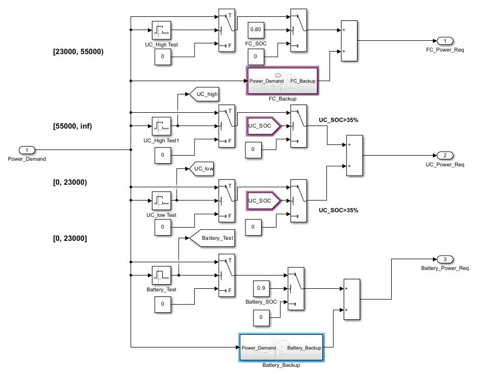
- From 0 to 23 KW is drawn from battery unit based on its SOC condition.
- Above 23KW to 55KW will be drawn from fuel cell power.
- And above 55KW will be drawn from ultracapacitors based on its SOC condition.
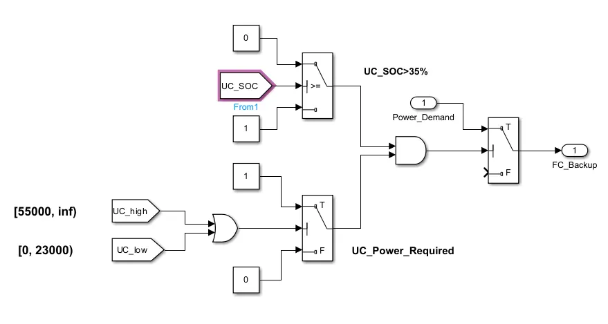
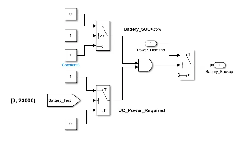
So, If SOC of UC is not enough to supply required power demand in that case the power is drawn from battery as battery backup.
If SOC of battery and UC are not enough to supply power demand in that case alternate source is only fuel cell.
Here the Power is drawn from fuel cell as fuel cell backup.
But at these operating conditions the overall efficiency of vehicle is reduced as fuel cell can’t support with full efficiency for peak power demands and lesser power demands.
Simulink Model :-
The Simulink model of the Emnergy Management stratagy will be as followes.
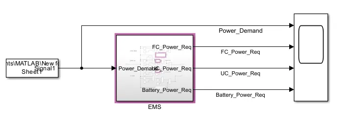
Procedure:-
The Positive power Subssystemis as followes,
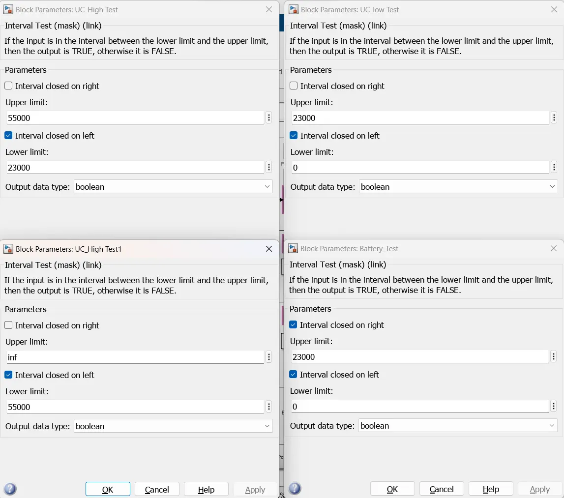
The Interval test block with following parameters.
FC Backup Block:
Battery Backup Block:
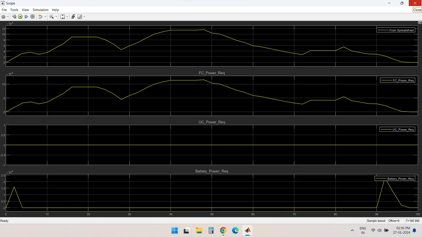
The resulting scope is as given below,