Week 9 Challenge
CPU FAN CASE MOLD DESIGN
OBJECTIVE:
To design a mold along with sliders, washers, inserts, core and cavity blocks for the given CPU FAN CASE.
DESIGN PROCEDURE:
Creation of core and cavity blocks are done in in the previous challenge.In this challenge I was designed the remaining parts like slider, washers, locking mechanism and inserts.
DESIGN OF SLIDER_01:
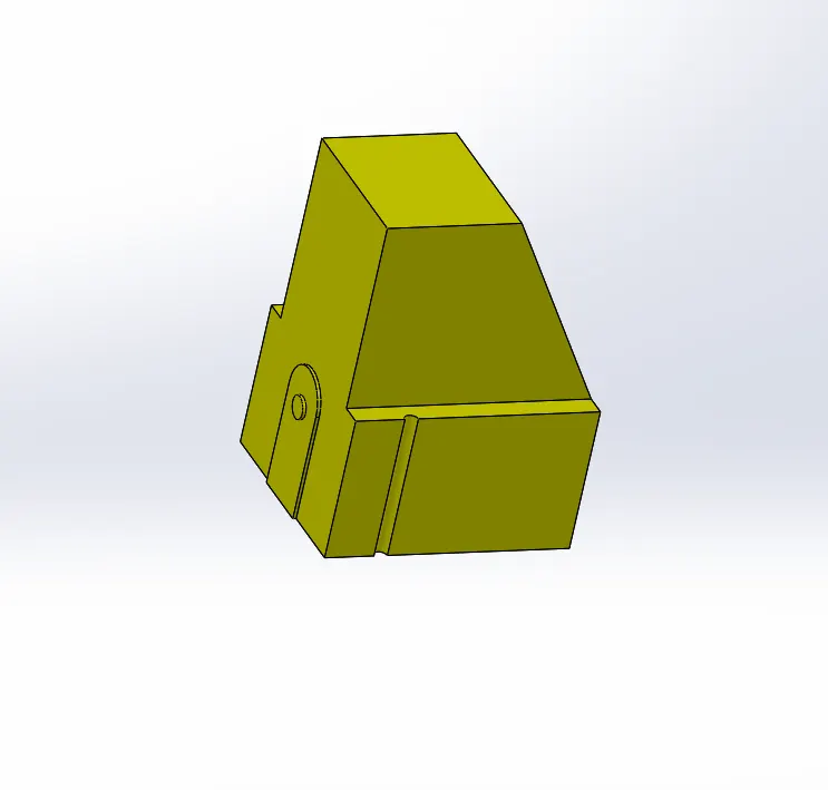
TOOLS USED:
- REFERENCE PLANE
- SPLIT
- SKETCH
- EXTRUDE CUT
- FILLET
- EXTRUDE BOSS
- COMBINE
- DELETE OR KEEP BODY
- INSERT NEW PART
REFERENCE PLANE:
Slider_01 is created on core part, so activate the core and start to work on it.
Reference plane is created on the perpendicular face of the undercut.
SKETCH:
Sketch is created covering the undercut and exit the sketch.
SPLIT:
Now use split command under the direct editing toolbar and select the reference plane and the sketch and click the cut bodies.
Now the body is split into two parts , click the slider part and click ok.Now the slider part is created.
EXTRUDED BOSS:
Then select the same plane and click the undercut hole and convert entities.Now the sketch is created on the plane , use extruded boss command and ectrude it to the end of the hole.
select the body ( slider body) for merge body.
EXTRUDE CUT:
The is created to the full length of the mold block , we have to cut the slider , so there will be a space for slider to slide.
Create a sketch and click the exturde cut command .
FILLET:
Fillet is given in the top face to remove sharp edges.
Now the slider_01 part is created click insert into new part and save it in parasolid format.
DELETE OR KEEP BODY:
Click the delete or keep body to delect the slider body.
INSERT NEW PART:
Now get back to the assembly and click the insert new part and rename it as SLIDER_01.
GO to insert>Features>import and slect the slider_01 and import the slider part.
DESIGN OF SLIDER_02:
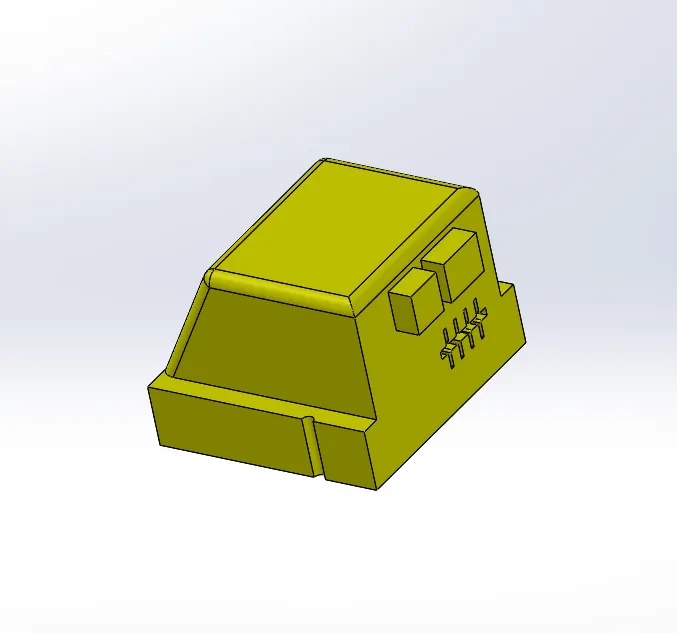
TOOLS USED:
- REFERENCE PLANE
- SPLIT
- SKETCH
- EXTRUDE CUT
- FILLET
- EXTRUDE BOSS
- COMBINE
- DELETE OR KEEP BODY
- INSERT NEW PART
The SLIDER_02 is created on both core and the cavity part and combine in into single slider part.
First activate the core part and start to work on it.
REFERENCE PLANE:
Reference plane is created on the perpendicular face of the undercut.
SKETCH:
Sketch is created covering the undercut and exit the sketch.
SPLIT:
Now use split command under the direct editing toolbar and select the reference plane and the sketch and click the cut bodies.
Now the body is split into two parts , click the slider part and click ok.Now the slider part is created.
Then click insert into new part and save it as slider_02_core
Now activate the cavity part and follow the same procedure and save it as Slider_02_cavity
INSERT NEW PART:
Get back to assembly and click insert new part and rename it as SLIDER_02.
Go to insert>Features>import and click slider_02_core and import it into the slider_02 part.
do the same steps to import the sllider_02_cavity.
COMBINE:
After importing the slider_02_core and slider_02_cavity, use combine command to combine both the slider cor and slider cavity.
EXTRUDE CUT:
The is created to the full length of the mold block , we have to cut the slider , so there will be a space for slider to slide.
Create a sketch and click the exturde cut command .
FILLET:
Fillet is given in the top face to remove sharp edges.
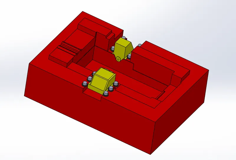
Now sliders are created.Then we have to create washers and locking mechanism for the slider.
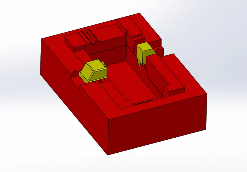
DESIGN OF WASHERS:
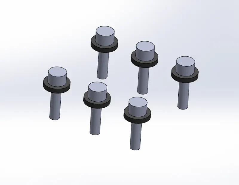
Washers are used to lock the sliders in position.
INSERT NEW PART:
IN ASSEMBLY insert the new part and rename it as washers_01 for the slider_01.
EXTRUDED BOSS:
Select the top face near to the slider and start a sketch.
the dia of washer should be 16mm and extrude it to 3mm.
and on the washer's top face create a sketch a circle of dia 11mm and extrude it upto 7mm
and on the bottom create a sketch a circle of dia 6mm and extrude it upto 22mm
Follow the same procedure for the Washer_02 For slider_02.
INSERTS:
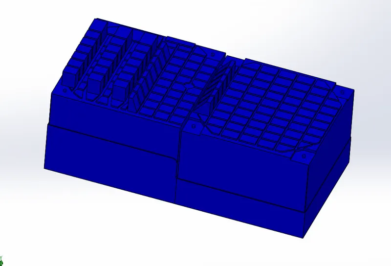
Inserts are used in the places where the hole depth is more than the dia of the hole or where the length of the cut is more than the width of the cut.
In this model 2 inserts are created . The depth of the cut on the boundaries of the model is more than the wdth of the cut.
To create an insert select a bottom face and create a plane .The plane should created 50mm above the bottom of the mold to accomodate the bolts to fasten the inserts.
and create a sketch on top of the core block.
NOW USE SPLIT TOOL to split the core body. select the plane and the sketch and click cut bodies and select the insert part and click ok.
now the insert is created and save it as seperate part file and name it as insert.
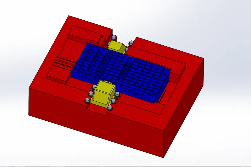
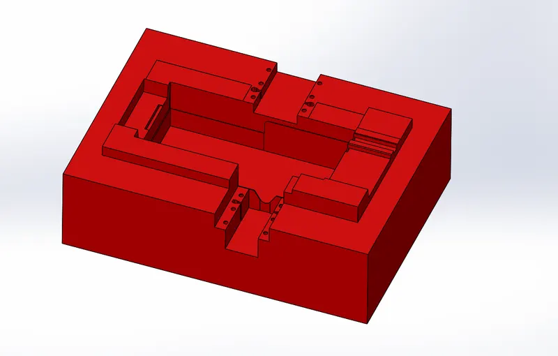
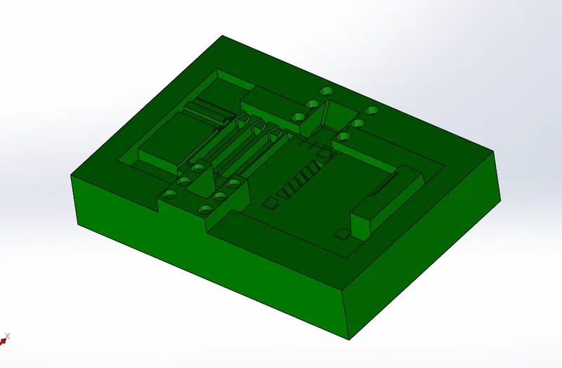
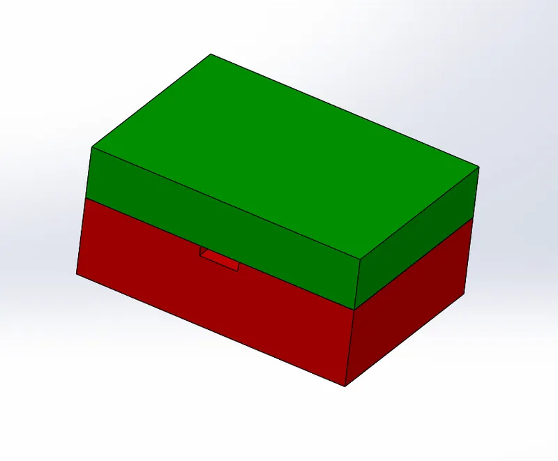
MOLD BLOCK IMAGES:
CONCLUSION:
Thus the creation of mold blocks for the given CPU FAN CASE is completed.